
Basics of Electricity
Every electronic device you use, from a simple LED to a sophisticated microcontroller, operates based on the same fundamental principles of electricity. Understanding these principles is not optional. It is foundational. You cannot design reliable circuits, debug hardware problems, or work with sensors without grasping what happens when electricity flows through a wire.
The good news: the core concepts are simple. This lesson covers the essential building blocks. Once you understand voltage, current, and resistance, everything else follows naturally.
What is electricity?
At its most basic, electricity is the flow of electrons through a conductor. An electron is a subatomic particle with a negative charge. When electrons move, they carry energy from one place to another. That movement is what we call current.
But before electrons can move, there must be a reason for them to move. That reason is an imbalance of charge: a place with an excess of electrons (negative) and a place with a deficit of electrons (positive). This imbalance creates an electric field, which pushes the electrons toward the positive side. We call this push voltage.

The path that the electrons follow is called a circuit. A complete circuit has three things: a source of voltage (like a battery), a path for current to flow (like a wire), and something that uses that current (like a resistor, LED, or motor). Break any part of the circuit, and the current stops.
Understanding electricity boils down to understanding three quantities that describe what is happening in any circuit: voltage, current, and resistance. Let's define each one clearly.
The Three Core Quantities: Voltage, Current, and Resistance
Every circuit problem, no matter how complex, can be reduced to these three quantities. Understanding what they are, physically and mathematically, is the gateway to understanding electronics.
Voltage: The Push
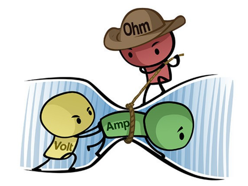
Voltage is the electrical potential difference between two points in a circuit. Think of it as pressure. Just as water pressure pushes water through a pipe, voltage pushes electrons through a wire.
The unit of voltage is the volt (V). A volt is formally defined as the energy (in joules) per unit charge (in coulombs) needed to move that charge between two points. In practice, all you need to know is: voltage is the electrical "push" that drives current.
Common voltage sources you will encounter:
- A typical AA battery: 1,5 V
- A USB power supply: 5 V
- The mains power in Europe: 230 V
- A microcontroller logic level: 3,3 V or 5 V
An important insight: voltage is relative. It always exists between two points. When we say a battery is "9 volts," we mean there is a 9-volt difference between its positive and negative terminals. We call the negative terminal "ground" and use it as our reference point (0 V). Everything else is measured relative to ground.
Current: The Flow
Current is the rate at which electrons flow through a circuit. If voltage is the push, current is the actual movement of charge.
The unit of current is the ampere (A), often shortened to "amp." One ampere is defined as one coulomb of charge flowing past a point per second. Smaller currents are written in milliamps (mA: thousandths of an amp) or microamps (µA: millionths of an amp).
Common current values in IoT projects:
- An LED: typically 10-20 mA
- A microcontroller: typically 50-200 mA
- A small motor: could be 500 mA to several amps
- A sensor on I2C: a few milliamps
Current flows in one direction: from the positive terminal of a voltage source, through the circuit, back to the negative terminal. This direction is called conventional current flow. (Historically, scientists thought positive charges were moving, but electrons are actually negative and move in the opposite direction. We stick with conventional current anyway because it is the standard in all technical documentation.)
Resistance: The Obstacle
Resistance is the opposition to the flow of current. Some materials allow electrons to flow easily (conductors, like copper). Others resist the flow strongly (insulators, like rubber). Resistance quantifies how much a material opposes current.
The unit of resistance is the ohm (Ω). A one-ohm resistor means that one volt will push one amp of current through it. Larger resistances are written in kilohms (kΩ: thousands of ohms) or megohms (MΩ: millions of ohms).
Common resistance values in circuits:
- Connecting wire: milliohms (nearly zero)
- An LED current-limiting resistor: typically 150 Ω to 10 kΩ
- A pull-up resistor: typically 1 kΩ to 100 kΩ
- A light-dependent resistor (LDR) in bright light: hundreds of ohms
- A light-dependent resistor (LDR) in darkness: megohms
The key insight is this: resistance is not a bad thing. It is a tool. By controlling resistance, we control how much current flows, and therefore how much power is dissipated. An LED needs a resistor in series with it, not because the resistor is wasting energy, but because the resistor protects the LED by limiting the current to a safe level.
Ohm's Law
Now we have three quantities. How do they relate to each other? The answer is Ohm's Law, one of the most fundamental equations in electronics:

Where:
- U is voltage (in volts)
- I is current (in amperes)
- R is resistance (in ohms)
Note: In Europe, we use the symbol U for voltage in formulas. You may also encounter V in some contexts, but U is the standard symbol in European electronics and electrical engineering. The unit remains "volt" (V).
This single equation unlocks almost everything. If you know any two of the three quantities, you can calculate the third. Rearranging:
Let's work through some examples to make this concrete.
Example 1: Calculating current through an LED
You have a 5 V power supply and a 220 Ω resistor. What current flows through the resistor?
Using Ohm's Law:
This is a safe current for a typical LED.
Example 2: Choosing a resistor
You want to limit current through an LED to 10 mA on a 3,3 V logic pin. What resistance do you need?
Using Ohm's Law:
A 330 Ω resistor would work. (You would use the next standard value available, which happens to be exactly 330 Ω.)
Example 3: Finding voltage across a component
You measure 50 mA flowing through a 100 Ω resistor. What is the voltage drop across it?
Using Ohm's Law:
A 50 mA current flowing through 100 Ω produces a 5 V drop.
Try it yourself!
For each scenario, use Ohm's Law to find the missing quantity.
Scenario 1: You have a 12 V supply and a 600 Ω resistor. Find the current.
Solution
Scenario 2: You measure 0,5 A flowing through a 100 Ω resistor. Find the voltage across it.
Solution
Scenario 3: A 5 V supply powers a circuit with 25 mA flowing. Find the total resistance.
Solution
Power and Wattage
Current flowing through resistance produces heat. This happens because the electrons are colliding with atoms, transferring energy. The rate at which energy is dissipated is called power.
Power is measured in watts (W). One watt is one joule of energy consumed per second. Just as voltage, current, and resistance are related by Ohm's Law, power is related to them by another fundamental equation:
Where:
- P is power (in watts)
- U is voltage (in volts)
- I is current (in amperes)
You can also substitute Ohm's Law to get two alternative forms:
All three equations are correct and useful. Which one you use depends on which quantities you know.
Why power matters in IoT
In embedded systems, power consumption directly determines battery life. A device drawing 100 mA from a 2000 mAh battery lasts 20 hours. The same device drawing 500 mA lasts only 4 hours. Power is not abstract, it is a critical design constraint.
Power also determines how much heat a component generates. A resistor dissipating 1 W will become hot. A resistor dissipating 0,1 W will barely warm up. Exceeding a component's power rating causes it to fail.
Example 1: Power dissipated in a resistor
You have a 220 Ω resistor with 25 mA flowing through it. How much power is dissipated?
Using the formula:
This is well within the limits of a standard 0,25 W resistor (which can safely dissipate up to 250 mW).
Example 2: Power supplied by a battery
A 5 V power supply delivers 2 A to a circuit. How much power is supplied?
Using the formula:
The power supply must be rated for at least 10 W to safely handle this load.
Example 3: Power through a resistor via voltage
A 1 kΩ resistor is connected across a 12 V supply. How much power does it dissipate?
Using the formula:
Try it yourself!
Question 1: A 5 V supply delivers 2 A to a circuit. How much power is supplied?
Solution
Question 2: A 100 mA current flows through a 100 Ω resistor. How much power is dissipated?
Solution
Question 3: A 1,5 kΩ resistor is connected across a 12 V supply. How much power does it dissipate?
Solution
Series and Parallel Circuits
Up until now, we have looked at simple circuits with one resistor. Real circuits often have multiple components. The way components are connected determines how voltage, current, and power are distributed.
There are two fundamental ways to connect components: in series and in parallel. Many circuits use a combination of both.
Series Circuits
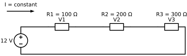
In a series circuit, components are connected one after another in a single path. Current has only one way to flow.
Key properties of series circuits:
Current is the same everywhere. The same current flows through every component. If 1A enters the first resistor, 1A exits it, flows through the next resistor, and so on.
Voltages add up. The voltage drops across each resistor add up to the total voltage supplied.
Resistances add up. The total resistance is the sum of all individual resistances.
Series example: Three resistors
Suppose you have three resistors in series with a 12 V supply:
- R1 = 100 Ω
- R2 = 200 Ω
- R3 = 300 Ω

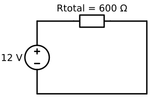
Find the total resistance:
We can simplify our circuit:
Find the current:
Find the voltage across each resistor:
Notice that V. The voltages add up to the supply voltage.
Also notice that larger resistors get larger voltage drops. This is because the current is the same through all of them, and U = I × R. A larger R means a larger U drop.
Parallel Circuits
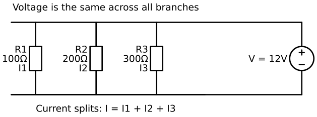
In a parallel circuit, all components are connected across the same two points. There are multiple paths for current to flow.
Key properties of parallel circuits:
Voltage is the same everywhere. Every component experiences the full supply voltage.
Currents add up. The currents through each branch add up to the total current from the supply.
Resistances combine differently. The formula for total resistance is:
Or equivalently:
An important observation: the total resistance is always less than the smallest individual resistance. This is because parallel paths give current more ways to flow, reducing overall opposition.
Parallel example: Three resistors
Suppose you have three resistors in parallel with a 9 V supply:
- R1 = 100 Ω
- R2 = 200 Ω
- R3 = 300 Ω
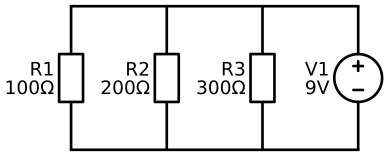
Find the total resistance:
Simplified circuit:

Find the current through each resistor:
Since all resistors experience 9 V:
Find the total current:
Verify using Ohm's Law:
Notice that the resistor with the smallest resistance carries the most current. This makes sense: less resistance means easier path for current to flow.
Try it yourself!
Series circuit: A 9 V battery powers three resistors in series: 47 Ω, 100 Ω, and 150 Ω.

Question 1: What is the total resistance?
Solution
Question 2: What is the current through the circuit?
Solution
Question 3: What is the voltage across the 100 Ω resistor?
Solution
Parallel circuit: A 12 V battery powers two resistors in parallel: 1 kΩ and 2 kΩ.
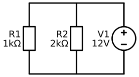
Question 1: What is the total resistance?
Solution
Question 2: What is the current through the 1 kΩ resistor?
Solution
Question 3: What is the total current?
Solution
Or: mA
Mixed (Series-Parallel) Circuits
Real circuits rarely use only series or only parallel. They mix both topologies. For example, you might have two parallel branches, each containing resistors in series.
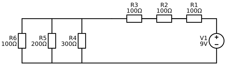
The strategy for solving mixed circuits is to break them into smaller chunks:
- Identify series and parallel groups.
- Simplify one group at a time, working from the simplest sub-circuits outward.
- Use Ohm's Law and power equations once you have simplified the circuit.
Mixed circuit example
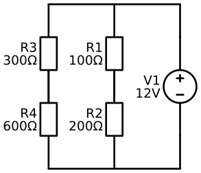
Consider a circuit with a 12 V supply and two parallel branches:
- Branch 1: 100 Ω and 200 Ω in series
- Branch 2: 300 Ω and 600 Ω in series
Step 1: Find the resistance of each branch.
Branch 1 resistance: Ω
Branch 2 resistance: Ω
Simplified circuit:

Step 2: Find the equivalent resistance of the two parallel branches.
Simplified circuit:

Step 3: Find the total current from the supply.
Step 4: Find the voltage across each branch (they are the same in parallel).
Both branches experience the full 12 V.
Step 5: Find the current through each branch.
Verify: mA
Reading Resistor Color Codes
A resistor is a physical component that you will see countless times in electronics projects. But how do you know its resistance value? It is marked with colored bands.
Resistor manufacturers use colored bands as a standardized way to label resistance values. This system dates back to the 1920s, before digital displays were common. It persists today because it works reliably and the labels are visible from any angle.
The color code system
Standard resistors have four bands (or sometimes five for precision components). The first three bands encode the value; the fourth band indicates tolerance (accuracy).
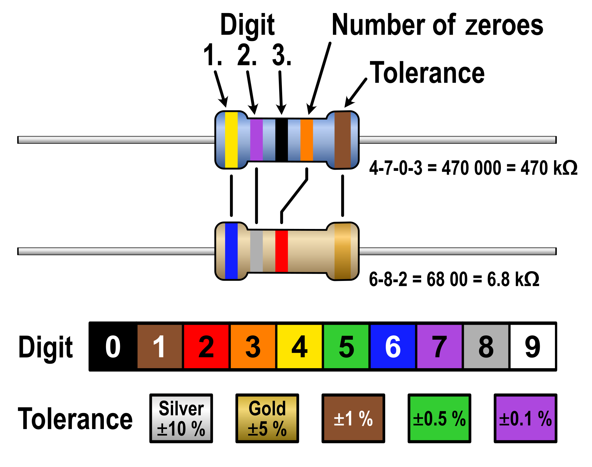
The color codes are:
| Color | Digit | Multiplier |
|---|---|---|
| Black | 0 | 10⁰ = 1 |
| Brown | 1 | 10¹ = 10 |
| Red | 2 | 10² = 100 |
| Orange | 3 | 10³ = 1,000 |
| Yellow | 4 | 10⁴ = 10,000 |
| Green | 5 | 10⁵ = 100,000 |
| Blue | 6 | 10⁶ = 1,000,000 |
| Violet | 7 | 10⁷ = 10,000,000 |
| Grey | 8 | - |
| White | 9 | - |
The tolerance band (fourth band) is typically gold (±5%), silver (±10%), or brown (±1%).
Reading a resistor: the memory aid
To memorize the color code, use this Dutch phrase:
"Zij bracht rozen op Gerrits graf bij vies grijs weer"
Breaking it down:
- Zij → Zwart (Black) = 0
- bracht → Bruin (Brown) = 1
- rozen → Rood (Red) = 2
- op → Oranje (Orange) = 3
- Gerrits → Geel (Yellow) = 4
- graf → Groen (Green) = 5
- bij → Blauw (Blue) = 6
- vies → Violet (Violet) = 7
- grijs → Grijs (Grey) = 8
- weer → Wit (White) = 9
(If you prefer English: "Bad Boys Respect Our Great Big Beautiful Women." But the Dutch phrase is more elegant.)
Example 1: A four-band resistor
Consider a resistor with bands: Brown, Black, Red, Gold
- First band (Brown): 1
- Second band (Black): 0
- Third band (Red): multiplier of 100
- Fourth band (Gold): ±5% tolerance
Value: 10 × 100 = 1000 Ω = 1 kΩ (±5%)
Example 2: Another four-band resistor
Consider a resistor with bands: Yellow, Violet, Orange, Brown
- First band (Yellow): 4
- Second band (Violet): 7
- Third band (Orange): multiplier of 1,000
- Fourth band (Brown): ±1% tolerance
Value: 47 × 1,000 = 47,000 Ω = 47 kΩ (±1%)
Example 3: Reading a physical resistor
You have a resistor with bands: Orange, Orange, Brown, Gold
- First band (Orange): 3
- Second band (Orange): 3
- Third band (Brown): multiplier of 10
- Fourth band (Gold): ±5% tolerance
Value: 33 × 10 = 330 Ω (±5%)
This is an extremely common value, the resistor used to limit current through LEDs on 5 V supplies.
Try it yourself!
Resistor 1: Bands are Brown, Black, Brown, Gold. What is the value?
Solution
- First band (Brown): 1
- Second band (Black): 0
- Third band (Brown): multiplier of 10
- Value: 10 × 10 = 100 Ω (±5%)
Resistor 2: Bands are Red, Red, Orange, Brown. What is the value?
Solution
- First band (Red): 2
- Second band (Red): 2
- Third band (Orange): multiplier of 1,000
- Value: 22 × 1,000 = 22 kΩ (±1%)
Resistor 3: Bands are Yellow, Purple, Yellow, Gold. What is the value?
Solution
- First band (Yellow): 4
- Second band (Purple): 7
- Third band (Yellow): multiplier of 10,000
- Value: 47 × 10,000 = 470 kΩ (±5%)
Resistor 4: Bands are Brown, Green, Red, Brown. What is the value?
Solution
- First band (Brown): 1
- Second band (Green): 5
- Third band (Red): multiplier of 100
- Value: 15 × 100 = 1,5 kΩ (±1%)
Five-band resistors
Some precision resistors have five bands instead of four. The first three bands represent the digits (instead of two), and the fourth band is the multiplier. The fifth band is the tolerance.
For example, a resistor with bands Brown, Black, Brown, Brown, Brown would be:
- First band: 1
- Second band: 0
- Third band: 1
- Fourth band: multiplier of 10
- Fifth band: ±1% tolerance
Value: 101 × 10 = 1,010 Ω (±1%)
The logic is the same; there is simply one more digit encoded.
Key Takeaways
Before moving on to more complex circuits, make sure you understand these core ideas:
Voltage is electrical potential difference. It is the "push" that drives current, measured in volts.
Current is the flow of electrons. It is the rate of charge movement, measured in amps.
Resistance opposes current flow. It is a property of materials, measured in ohms.
Ohm's Law ties them together: . If you know any two, you can find the third.
Power is the rate of energy dissipation: (or or ). Power matters for battery life and component ratings.
Series circuits share current and divide voltage. Total resistance is the sum.
Parallel circuits share voltage and divide current. Resistances combine with reciprocals.
Resistor color codes encode resistance value using colored bands. Learning the mnemonic makes reading them automatic.
These fundamentals are not just theory. Every circuit you design will depend on understanding them. The good news is that once these concepts are solid, you have the tools to analyze any circuit made of resistors and power supplies.
Glossary: Key Terms and Abbreviations
This section defines important terms and abbreviations used in this lesson. You will encounter these frequently as you study electricity and electronics.
A (Ampere)
The unit of electric current. One ampere represents one coulomb of charge flowing past a point per second. Common abbreviation: A or mA (milliamp = 1/1000 amp).
Ampere (A)
See A (Ampere).
Circuit
A complete path through which electric current can flow. A circuit requires three components: a source of voltage (like a battery), a conductor (like a wire), and a load (like a resistor or LED).
Conductor
A material that allows electric current to flow easily through it. Copper and aluminum are common conductors used in electronics.
Coulomb
A unit of electric charge. One coulomb equals the charge carried by 6.24 × 10¹⁸ electrons.
Current
The flow of electric charge through a circuit. Measured in amperes (A). Current represents how much charge is flowing per second.
Electron
A negatively charged subatomic particle. The flow of electrons creates electric current.
Insulator
A material that resists the flow of electric current. Rubber, plastic, and glass are common insulators used to protect conductors.
I2C (Inter-Integrated Circuit)
A common communication protocol used between electronic devices (like sensors and microcontrollers) to exchange data over two wires.
LED (Light-Emitting Diode)
An electronic component that emits light when current flows through it. LEDs are commonly used as indicators in circuits and require a resistor in series to limit the current to a safe level.
LDR (Light-Dependent Resistor)
A component whose resistance changes based on how much light hits it. LDRs are used in light sensors and automatic lighting systems.
mA (Milliamp)
One thousandth of an ampere (0,001 A). Often used to describe small currents in electronics.
Microcontroller
A small computer on a single chip that can be programmed to control electronic circuits. Examples: Arduino, Raspberry Pi.
Ω (Ohm)
The unit of electrical resistance. One ohm represents the resistance that allows one ampere of current to flow when one volt is applied.
Ohm's Law
The fundamental relationship between voltage, current, and resistance: U = I × R. This law is essential for analyzing any circuit.
Pull-up Resistor
A resistor used in circuits to ensure a digital signal has a known state (high or low) when no other device is driving it.
Resistance
The opposition to the flow of electric current. Measured in ohms (Ω). Every material has some resistance; some conduct easily (low resistance) while others oppose current flow strongly (high resistance).
Resistor
A component designed to have a specific resistance value. Resistors are used to limit current, divide voltage, and control how circuits behave.
Sensor
A device that detects a physical quantity (like light, temperature, or motion) and converts it into a signal that a circuit can use.
Tolerance
The acceptable range of error for a component's value. For example, a resistor with a ±5% tolerance could have a resistance up to 5% higher or lower than its labeled value.
V (Volt)
The unit of electrical potential difference (voltage). One volt is the energy per unit charge needed to move charge between two points.
Voltage
The electrical potential difference between two points. Often called the "push" that drives current through a circuit. Measured in volts (V).
Watt (W)
The unit of electrical power. One watt equals one joule of energy consumed per second. Watts tell you how much energy a device uses per second.
Extra Resources
https://learn.sparkfun.com/tutorials/voltage-current-resistance-and-ohms-law/