
Numeral Systems
Every day, without thinking about it, you count using ten symbols: 0 through 9. After 9 you start a new column to the left to get 10, then 11, and eventually 99, 100, and so on. This system feels completely natural because it is the one you have used since childhood. But there is nothing fundamentally special about using ten symbols. It is a convention that humans adopted, most likely because we have ten fingers.
In computing, a different convention is used. Learning to read and convert between numeral systems is an essential skill for anyone working with microcontrollers or IoT devices. Register values in datasheets, memory addresses, colour codes in firmware, network packets. All of these involve numbers written in bases other than ten.
What is a numeral system?
A numeral system is an agreement about how to represent quantities using symbols. You could use any symbols you like. What matters is the rule for combining them. The decimal system uses ten symbols (0 through 9), but you could equally invent a system using pictures, letters, or any other set of distinct symbols.
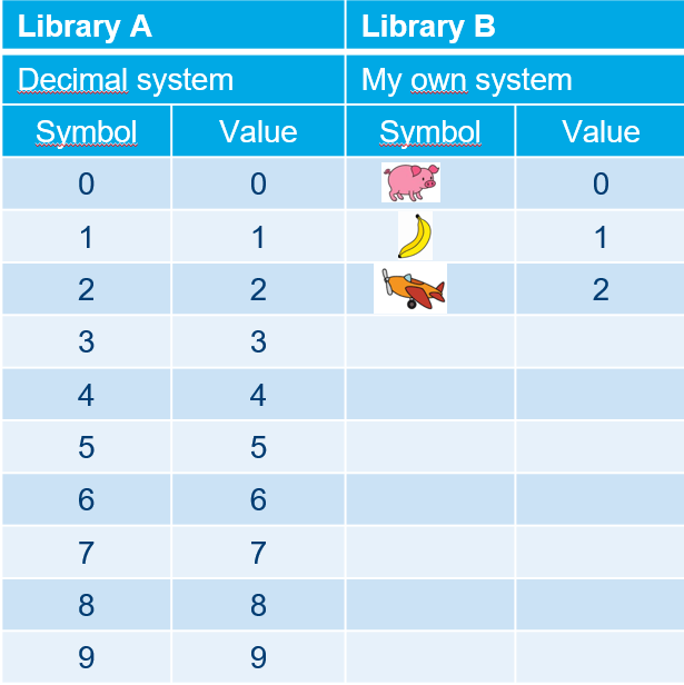
What all positional numeral systems share is the concept of positional notation: the value of a symbol depends not just on what symbol it is, but on its position within the number. In the decimal number 342, the 3 does not represent three. It represents three hundreds, because it sits in the hundreds column. Each position carries a weight that is a power of the base.
The same principle applies to every numeral system. The only thing that changes is the base: instead of powers of ten, positions carry powers of whatever base you are using.
| System | Base | Symbols |
|---|---|---|
| Decimal | 10 | 0 ... 9 |
| Binary | 2 | 0 ... 1 |
| Hexadecimal | 16 | 0 ... F |
Why do computers use binary?
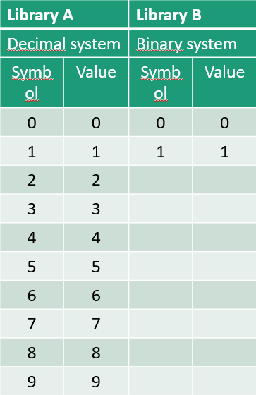
A computer is built from billions of tiny electronic switches called transistors. Each transistor has two stable states: it is either conducting (current flows through it) or not conducting (no current). These two states map naturally onto the symbols 1 and 0.

The reason computers do not use the decimal system is that it would require circuits capable of reliably distinguishing ten different voltage levels. One for each digit from 0 to 9. That is technically possible, but it is far less reliable and far harder to manufacture at scale. A binary circuit only needs to answer one question: is there voltage present, or not? This simplicity makes binary systems robust, fast, and inexpensive to produce.
As an IoT engineer, you will regularly encounter this directly. A GPIO pin on a microcontroller is either HIGH or LOW. A sensor reading arrives as a stream of bits. A register in a chip is a collection of 1s and 0s, each controlling a specific behaviour. Understanding binary is not abstract theory. It is how the hardware you work with actually functions.
Advantages and disadvantages of binary
The simplicity of binary comes with a trade-off. With only two symbols, you cannot say very much with a single digit. A single binary digit (called a bit) can only represent one of two values: 0 or 1. To represent larger numbers, you need long sequences of bits, which can become difficult to read and write.
For example, the decimal number 844 is 0000001101001100 in binary. That's sixteen characters to write what takes three in decimal. This is why binary is never used as a notation in documentation or code. Instead, programmers use hexadecimal as a compact shorthand (more on that later).
From a hardware perspective, the trade-off is similar. A binary system needs more individual signal lines (copper tracks on a circuit board) than a decimal system would for the same information. But each line is far simpler to build reliably. This is the fundamental compromise that underlies all digital electronics.
Bits, nibbles and bytes
A single bit is the smallest unit of information in a computer. It holds exactly one binary digit: a 0 or a 1. On its own, that is not very useful. One bit can answer one yes/no question: is the LED on? Is the button pressed? Is the sensor triggered?
To represent larger values, bits are grouped together. The most common groupings have specific names:
| Name | Number of bits | Example |
|---|---|---|
| Bit | 1 | 1 |
| Nibble | 4 | 1010 |
| Byte | 8 | 1010 1100 |
| Word | 16, 32 or 64 | depends on the processor |
A byte is the most fundamental unit in practice. A single byte can represent 256 different values (0 through 255), which is enough for things like a single character of text, a sensor reading, or the value of a register in a microcontroller. When you read a temperature sensor over I2C, the data typically arrives as one or two bytes. When you configure a pin on an Arduino by writing to a register, you are writing a byte.
Why this matters in IoT
Before diving into the conversions, it is worth pausing to understand why numeral systems actually come up in IoT work. Here are a few concrete examples.
When you look up the datasheet for a sensor or a chip, register addresses and configuration values are almost always written in hexadecimal. A line like write 0x1E to register 0x40 is completely normal. If you do not know how to read hexadecimal, that datasheet is unreadable.
When you debug a communication protocol like UART or I2C using a logic analyser, the captured data is displayed as a stream of bytes in hexadecimal. Recognising patterns like 0xFF (all bits set) or 0x00 (all bits cleared) helps you understand what is happening on the bus.
When you control hardware directly through registers: for example, setting which pins are output pins on an AVR microcontroller. You are writing binary patterns into registers. Understanding which bit controls which pin is essential for low-level programming.
Reading a binary number
A binary number is read in exactly the same way as a decimal number, just using powers of two instead of powers of ten. Starting from the rightmost position (position 0) and moving left, each position is worth double the previous one.
| Position | 7 | 6 | 5 | 4 | 3 | 2 | 1 | 0 |
|---|---|---|---|---|---|---|---|---|
| Value | 128 | 64 | 32 | 16 | 8 | 4 | 2 | 1 |
To find the decimal value of a binary number, you look at each bit position and add up the weights of all the positions where the bit is 1.
Binary to decimal: step by step
Take the binary number 0000 1101. Working through each bit from left to right:
| Value | 128 | 64 | 32 | 16 | 8 | 4 | 2 | 1 |
|---|---|---|---|---|---|---|---|---|
| Bit | 0 | 0 | 0 | 0 | 1 | 1 | 0 | 1 |
The bits that are 1 sit in the positions worth 8, 4 and 1. Adding those up: 8 + 4 + 1 = 13.
So 0000 1101 in binary equals 13 in decimal.
Try it yourself!
Convert the following binary numbers to decimal:
| Binary | Decimal |
|---|---|
0000 0111 | ? |
0010 1010 | ? |
0001 0001 | ? |
Solution
| Binary | Decimal | Calculation |
|---|---|---|
0000 0111 | 7 | 4 + 2 + 1 = 7 |
0010 1010 | 42 | 32 + 8 + 2 = 42 |
0001 0001 | 17 | 16 + 1 = 17 |
Decimal to binary
Going in the other direction: from decimal to binary. This uses a process of repeated division by 2. Each time you divide, the remainder (which is always 0 or 1) becomes one bit of the binary result. You keep dividing the quotient until it reaches 0, then read the remainders from bottom to top.
This method works because each division essentially answers the question: "does this number have a 1 in the current bit position?" The remainder tells you, and you shift to the next position by dividing by two.
Decimal to binary: step by step
Take the decimal number 13:
| Step | Division | Result | Remainder |
|---|---|---|---|
| 1 | 13 / 2 | 6 | 1 |
| 2 | 6 / 2 | 3 | 0 |
| 3 | 3 / 2 | 1 | 1 |
| 4 | 1 / 2 | 0 | 1 |
Reading the remainders from bottom to top gives 1101. Padded to 8 bits, the result is 0000 1101. This matches what we converted from binary above.
Try it yourself!
Convert the following decimal numbers to binary:
| Decimal | Binary |
|---|---|
| 7 | ? |
| 42 | ? |
| 5 | ? |
Solution
| Decimal | Binary |
|---|---|
| 7 | 0000 0111 |
| 42 | 0010 1010 |
| 5 | 0000 0101 |
Hexadecimal
Binary numbers get unwieldy very quickly. Writing 0011 0100 1100 instead of 844 is error-prone and hard to read. Hexadecimal (base 16) exists precisely to solve this problem. It is a compact notation for binary data that is widely used in programming, datasheets, and debugging tools.
Hexadecimal has 16 symbols. It uses the regular digits 0 through 9 and then continues with the letters A through F for the values 10 through 15.
| Decimal | 10 | 11 | 12 | 13 | 14 | 15 |
|---|---|---|---|---|---|---|
| Hex | A | B | C | D | E | F |
The reason hexadecimal works so well as a shorthand for binary is that 16 is exactly 2 to the power of 4. This means one hexadecimal digit always represents exactly 4 bits (one nibble). Converting between binary and hexadecimal is therefore completely mechanical. No arithmetic needed, just substitution.
In code, hexadecimal values are typically written with a 0x prefix, so 0x2A means 2A in hexadecimal.
Reference table
| Binary | Hex | Decimal |
|---|---|---|
0000 | 0 | 0 |
0001 | 1 | 1 |
0010 | 2 | 2 |
0011 | 3 | 3 |
0100 | 4 | 4 |
0101 | 5 | 5 |
0110 | 6 | 6 |
0111 | 7 | 7 |
1000 | 8 | 8 |
1001 | 9 | 9 |
1010 | A | 10 |
1011 | B | 11 |
1100 | C | 12 |
1101 | D | 13 |
1110 | E | 14 |
1111 | F | 15 |
Binary to hexadecimal
To convert binary to hexadecimal, split the bits into groups of 4 from the right (nibbles) and replace each group with the corresponding hex digit.
Take 0010 1010 as an example. It is already split into two nibbles:
| Nibble | Binary | Hex |
|---|---|---|
| Left | 0010 | 2 |
| Right | 1010 | A |
Result: 0010 1010 = 0x2A. What took 8 characters in binary takes just 2 in hexadecimal.
Hexadecimal to binary
Going the other way is equally straightforward. Replace each hex digit with its 4-bit equivalent from the reference table above.
For 0x2A:
| Hex digit | Binary |
|---|---|
| 2 | 0010 |
| A | 1010 |
Result: 0x2A = 0010 1010 in binary.
Negative numbers
Everything covered so far has dealt with positive numbers. But in practice, you often need to represent negative values too. A temperature below zero. A direction. A signed sensor offset. This raises an important question: how do you represent a negative number in a system that only knows 0s and 1s?
The most intuitive approach would be to dedicate one bit as a sign bit: 0 for positive and 1 for negative. This is called sign-magnitude representation.
| Bit 7 | Meaning |
|---|---|
| 0 | Positive |
| 1 | Negative |
Using sign-magnitude, 0000 1101 would be +13 and 1000 1101 would be -13. This seems clean, but there is a serious problem: this scheme produces two different representations of zero. 0000 0000 for positive zero and 1000 0000 for negative zero. This breaks basic arithmetic and causes bugs in hardware circuits.
Two's complement
The solution used by virtually every modern processor is called two's complement. It is a cleverer encoding that avoids the double-zero problem. Importantly, it means that addition and subtraction work with exactly the same hardware circuitry regardless of whether numbers are positive or negative.
In two's complement, positive numbers look exactly the same as in standard unsigned binary. Negative numbers are encoded differently. To find the two's complement representation of a negative number, you start from the positive version and apply two steps: flip all the bits (producing what is called the one's complement), then add 1.
Here is the full process for -13:
Step 1: Start with +13 in binary: 0000 1101
Step 2: Flip all bits (one's complement): 1111 0010
Step 3: Add 1: 1111 0010 + 1 = 1111 0011
So -13 in two's complement is 1111 0011. You can verify this works by noting that 0000 1101 + 1111 0011 = 1 0000 0000. Once the carry bit beyond 8 bits is discarded, the result is 0000 0000. Exactly zero, as expected.
The range of an 8-bit two's complement number is -128 to +127. The most significant bit still indicates the sign (0 = positive, 1 = negative), but the encoding of negative values is different from sign-magnitude.
Keep the bit width in mind
When you convert a number to two's complement, the number of bits matters. -13 in 8 bits is 1111 0011, but in 16 bits it is 1111 1111 1111 0011. Always work with a fixed bit width.
Overflow
Even without negative numbers, there is a fundamental limitation to working with a fixed number of bits: a byte can only hold values from 0 to 255. What happens when a calculation exceeds that range?
When the result of an addition is too large to fit in the available bits, the extra high-order bits are simply lost. This is called overflow. Consider adding 1 to 255 in an 8-bit register:
| Binary | |
|---|---|
| 255 | 1111 1111 |
| + 1 | 0000 0001 |
| Result | 1 0000 0000 |
The true result would be 256, which needs a 9th bit. Since the register is only 8 bits wide, that 9th bit is discarded and the value stored in the register becomes 0000 0000. Which is 0. The counter has wrapped around.
This is not a theoretical edge case. In embedded systems, overflow happens regularly in timing code, sensor accumulators and communication buffers. Recognising when it can occur and accounting for it is an important part of writing reliable firmware.
Overflow in practice
A common source of bugs in microcontroller code is an 8-bit or 16-bit variable that overflows unexpectedly. If a loop counter wraps around to 0 or a timer register overflows mid-calculation, the resulting behaviour can be very difficult to debug. Always consider the range of your variables.