
Lab 1: Basics of Electricity
1. Assignment description
In this lab you build your first circuits and you learn to use the three tools you will need for the rest of this course: the bench power supply, the digital multimeter and the breadboard.
You will not only build circuits. For every circuit you first predict what the meter will show, and only then you measure. That is the whole point of this lab: theory tells you what should happen, the meter tells you what really happens, and you learn to explain the difference.
What we expect:
- Every measurement table filled in, with units
- A short calculation next to every prediction
- Photos of your setups where indicated
- A short reflection of approximately half a page in Chapter 3
Planning
| When | Steps | What you do |
|---|---|---|
| Theory lesson (last 1,5 h) | 2.1 to 2.4 | Learn the instruments, read and measure resistors, map the breadboard |
| Lab session (3 h) | 2.5 to 2.10 | Ohm's law, series, parallel, mixed circuits, power and current limiting |
| If you finish early | 2.11 to 2.13 | Potentiometer, light sensor, LED. Not graded |
What do we need for the whole lab?
- 1x bench power supply (in the lab room)
- 1x digital multimeter with test leads (in the lab room)
- 1x breadboard
- Jumper wires (male to male)
- Resistors from your kit: 100 Ω, 220 Ω, 1 kΩ (3x), 4,7 kΩ, 10 kΩ
- Optional steps: 1x 10 kΩ potentiometer, 1x LDR, 1x red LED
Safety rules for the whole lab
- This supply has no output button: the terminals are live as soon as the unit is switched on. Turn the voltage down to 0 V before you change anything in your circuit.
- Set the current limit before you connect your circuit. It is your safety net.
- The resistors in your kit are 0,25 W types. Always check the power before you switch on.
- Never measure resistance on a circuit that is powered. See the warning in step 2.2.
- Never connect the multimeter in current mode directly across the power supply. See the warning in step 2.2.
2. Lab
2.1 The bench power supply
The bench power supply is an adjustable battery. You tell it which voltage you want and it delivers that voltage, from 0 V up to tens of volts. It also protects your circuit: you can tell it the maximum current it is allowed to deliver.
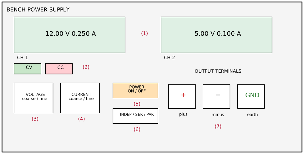
| Nr | Control | What it does |
|---|---|---|
| 1 | Display | Shows the voltage (V) and the current (A) that the supply is delivering right now |
| 2 | CV / CC indicator | CV = constant voltage, the supply gives the voltage you asked for. CC = constant current, the supply hit the current limit and lowers the voltage |
| 3 | VOLTAGE knob | Sets the output voltage. Coarse for big steps, fine for small steps |
| 4 | CURRENT knob | Sets the maximum current. This is not the current your circuit will draw, it is the ceiling |
| 5 | POWER switch | Switches the whole unit on or off. There is no separate output button per channel |
| 6 | INDEP / SER / PAR | Two channels working separately, in series or in parallel. We always use INDEP |
| 7 | Terminals | Red = +, black = −, green = earth (we do not use the green one) |
Important: there is no output button
The terminals of this supply are live from the moment the unit is switched on. So when a step in this lab says switch the supply off, it means: turn the VOLTAGE knob down to 0 V, and pull the red wire out of the + rail before you rebuild your circuit.
Important: the current display
Your circuit decides how much current it takes. The supply only decides the voltage. If the display shows 0,005 A, that is what your circuit is drawing, not what the supply is pushing into it.
Step 1: Switch on and set a voltage
- Before you switch on: turn the VOLTAGE knob fully to the left, and the CURRENT knob fully to the left as well.
- Switch the unit on with the POWER switch. Nothing is connected to the terminals.
- Open the CURRENT knob about a quarter turn. With the current knob fully closed, the supply will not let the voltage rise at all.
- Set the voltage to 5,00 V as precisely as you can.
- Look at the current display.
How much current does the supply deliver with nothing connected? Why?
Step 2: Set the current limit
The current limit is the most useful safety feature on the whole bench. If you wire something wrong, the supply refuses to deliver more than the limit and nothing burns.

- Turn the VOLTAGE knob fully to the left (0 V), and the CURRENT knob fully to the left as well.
- Open the CURRENT knob slowly, just far enough that you are able to set the voltage to about 1 V. As long as the current knob is fully closed, the display stays at 0 V, whatever you do with the voltage knob.
- Now connect a wire from the + terminal straight to the − terminal: a short circuit, on purpose, at 1 V.
- A piece of wire cannot hold 1 V, so the voltage collapses to almost zero and the supply switches to CC. The current display now shows exactly what the CURRENT knob allows.
- Turn the CURRENT knob until the display reads 0,10 A (100 mA).
- Remove the wire and set the voltage you need for your circuit.
Your supply is now limited to 100 mA. For the rest of this lab, leave it there unless a step says otherwise.
Take a picture of the display while the supply is in CC mode.
Why do we make this short circuit at 1 V, and not at 12 V?
2.2 The multimeter
The multimeter is one instrument with three completely different jobs: measuring voltage, measuring current and measuring resistance. The rotary switch decides which job it does. Choosing the wrong job is the number one way students destroy a meter, so read this step carefully.

| Nr | Part | What it does |
|---|---|---|
| 1 | Display | Shows the measured value. Watch the unit: V, mV, A, mA, Ω, kΩ, MΩ |
| 2 | Rotary switch | Chooses the measurement: V DC, V AC, Ω, continuity, mA, A |
| 3 | 10 A jack | Red lead goes here only for large currents. Behind it sits a fuse |
| 4 | V Ω mA jack | Red lead goes here for everything else |
| 5 | COM jack | Black lead always goes here |
The three jobs
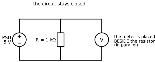
Voltage: the meter goes in parallel
Voltage is a difference between two points, so you hold the two probes on two points of a working circuit. You do not have to change your wiring at all.
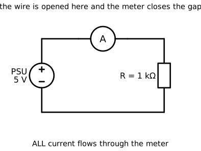
Current: the meter goes in series
Current flows through something. To measure it you have to open the circuit and let the current flow through the meter.
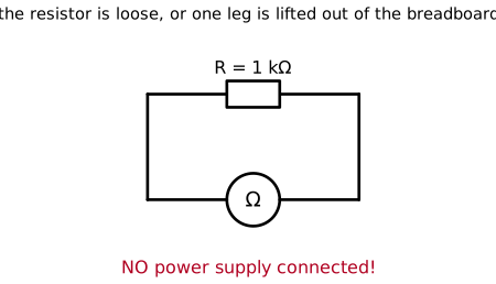
Resistance: the component comes out of the circuit
In Ω mode the meter sends a small current of its own through the component and measures what comes back. That only works if nothing else is connected and no power is present.
Never measure resistance on a powered circuit
The Ω mode expects to be the only source of energy. If you put the probes on a component while the power supply is switched on, you push the supply voltage into a measuring circuit that was built for a few microamps.
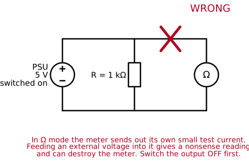
What happens:
- The reading is nonsense, because the meter cannot tell its own test current apart from the current that the supply pushes through.
- With a bench supply at a few volts you usually blow the internal protection or the fuse.
- With a higher voltage you burn the input stage and the meter is dead.
Rule: voltage down to 0 V, wire out of the + rail, and at least one leg of the component lifted out of the breadboard, before you turn the switch to Ω.
Never put the meter in current mode across the supply
In mA or A mode the meter is almost a plain piece of wire. Its resistance is a fraction of an ohm. Connect it straight across the + and − terminals and you have made a short circuit through your meter.
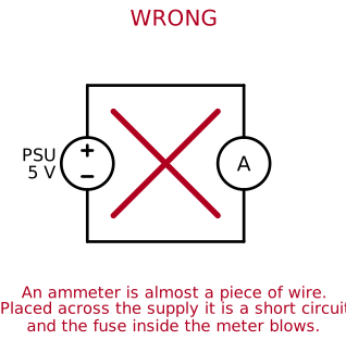
The fuse inside the meter blows, and a blown fuse means your measurement session is over. Current is always measured in series, never in parallel.
Step 1: Get to know your meter
- Put the black lead in COM and the red lead in V Ω mA.
- Set the switch to Ω and touch the two probe tips together. The display should go to about 0 Ω.
- Hold the probes apart. The display now shows OL or 1, which means "open line": infinite resistance.
- Set the switch to continuity (the sound symbol) and touch the probes together again. The meter beeps.
Write down what your meter shows in each of these three situations.
| Situation | Reading |
|---|---|
| Ω mode, probes touching | |
| Ω mode, probes apart | |
| Continuity mode, probes touching |
Step 2: Measure the supply voltage
- Set the supply to 5,00 V.
- Set the meter to V DC.
- Put the red probe on the + terminal and the black probe on the − terminal.
- Now swap the probes and look at the display again.
| Measurement | Reading |
|---|---|
| Red on +, black on − | |
| Red on −, black on + |
What is different in the second reading, and what does that tell you about voltage?
2.3 Reading and measuring resistors
Now you combine the colour code from the theory lesson with the Ω mode of the meter.
Take these resistors from your kit: 100 Ω, 220 Ω, 1 kΩ, 4,7 kΩ, 10 kΩ.
A band that is gold or silver
The third band is a multiplier. Gold means multiply by 0,1 and silver means multiply by 0,01. So red-red-black-gold is 22 × 1 = 22 Ω, while red-red-orange-gold is 22 × 1000 = 22 kΩ. Two very different resistors, one band apart. Check twice before you build.
Step 1: Read first, measure after
For each resistor: first write down the colours and the value you read from them. Then measure it with the meter in Ω mode. Do not measure first, you are training your eyes here.
Also calculate the tolerance window. A 1 kΩ resistor with a gold band (±5 %) is allowed to be anywhere between 950 Ω and 1050 Ω.
| Colours you see | Value you read | Tolerance window | Measured value | Inside the window? |
|---|---|---|---|---|
Did every resistor fall inside its tolerance window? If one did not, what could be the reason?
Step 2: A trap
Hold both metal probe tips between your thumb and index finger, one tip in each hand, with the meter in Ω mode.
What does the meter show? What are you measuring?
Now measure a 10 kΩ resistor while you squeeze both metal tips and both resistor legs firmly in your fingers.
Is the reading higher or lower than before? Explain why.
2.4 The breadboard
A breadboard lets you build a circuit without soldering. Inside it there are metal clips that connect groups of holes together. You have to know which holes are connected, otherwise you are guessing.
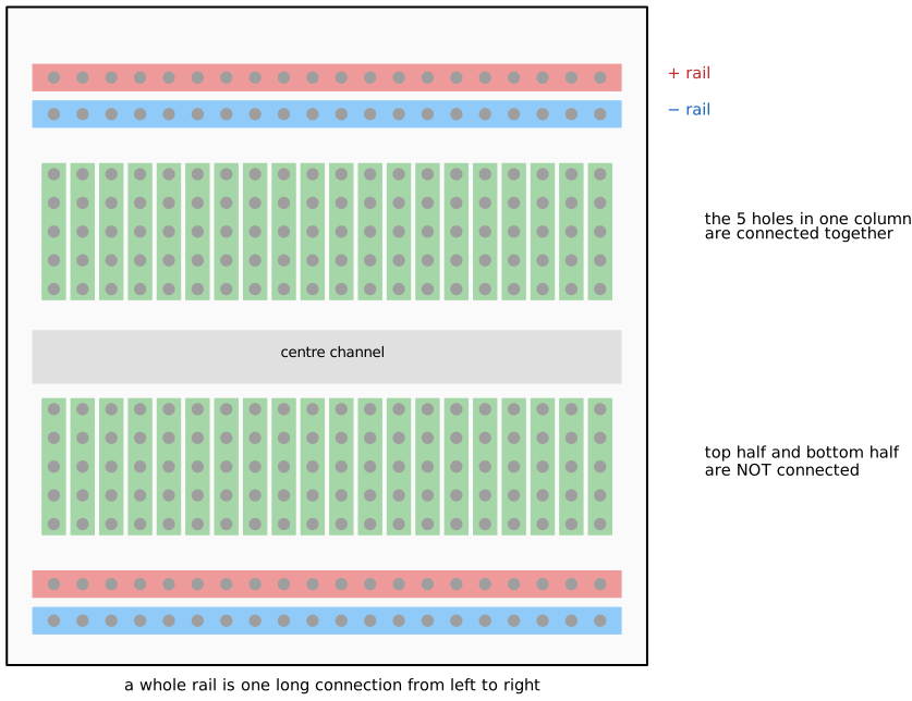
- The two long strips at the top and at the bottom are the power rails. Each rail is one long connection from left to right.
- In the middle field, every column of five holes is connected together.
- The centre channel splits the board: the top half and the bottom half are not connected.
Step 1: Prove it with the meter
Do not take our word for it, check it yourself. Put the meter in continuity mode. Push a short jumper wire into each hole you want to test and put the probes on the two wire ends.
| Test | Beep? | What does that prove? |
|---|---|---|
| Two holes in the same column (top half) | ||
| Two holes in the same row, but different columns | ||
| One hole above and one below the centre channel | ||
| Left end and right end of the same power rail | ||
| A hole in the + rail and a hole in the − rail |
Take a picture of your breadboard with the probes on the two points of the last test.
Step 2: Wire the rails
- Turn the voltage down to 0 V.
- Run a red wire from the + terminal of the supply to the + rail of your breadboard.
- Run a black wire from the − terminal to the − rail.
- Check with the continuity mode that the wires really make contact: one probe on the terminal, the other probe on a hole far away in the same rail.
You now have a powered breadboard. Leave this wiring in place for the rest of the lab.
2.5 Ohm's law with one resistor
Time to build. This is the smallest complete circuit there is: a supply and one resistor.
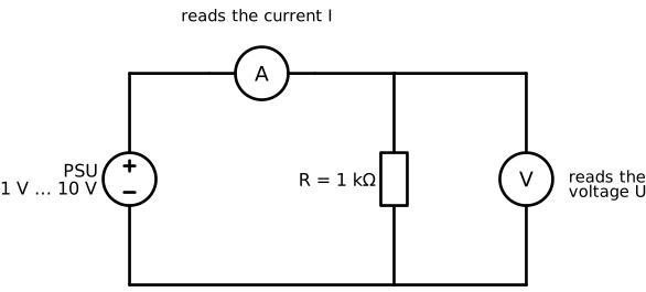
What do we need?
- 1x 1 kΩ resistor
- Breadboard and jumper wires
- Power supply set to 5 V, current limit 100 mA
- Multimeter
Step 1: Predict
Before you touch anything, calculate what the current will be.
I = U / R = 5 V / 1000 Ω = ... A = ... mA
Step 2: Build and measure the voltage
- Voltage down to 0 V. Place the resistor on the breadboard with its two legs in two different columns.
- Wire one leg to the + rail and the other leg to the − rail.
- Turn the voltage up to 5 V.
- Meter in V DC, probes on the two legs of the resistor.
Step 3: Measure the current
- Voltage down to 0 V.
- Take out the wire between the resistor and the + rail. Your circuit is now open.
- Meter in mA. Red lead still in the V Ω mA jack.
- Put the red probe on the + rail and the black probe on the free leg of the resistor. The meter now closes the gap.
- Turn the voltage back up to 5 V and read the current.
- When you are done: voltage down to 0 V, put the wire back, and turn the meter back to V DC.
| Quantity | Predicted | Measured |
|---|---|---|
| U over the resistor | ||
| I through the resistor |
Take a picture of your circuit with the meter connected in series.
Compare the current display of the power supply with the reading of your multimeter. Do they agree? Which one would you trust for a small current, and why?
2.6 The U-I graph
One measurement is a number. Eight measurements are a law. Keep the circuit from step 2.5 and leave the meter in series in mA mode.
Step 1: 1 kΩ
Set the supply to each voltage in the table and write down the current.
| U (V) | I calculated (mA) | I measured (mA) |
|---|---|---|
| 1 | ||
| 2 | ||
| 3 | ||
| 4 | ||
| 5 | ||
| 6 | ||
| 8 | ||
| 10 |
Step 2: 4,7 kΩ
Voltage down to 0 V, swap the 1 kΩ for a 4,7 kΩ resistor, and repeat.
| U (V) | I calculated (mA) | I measured (mA) |
|---|---|---|
| 1 | ||
| 2 | ||
| 5 | ||
| 10 |
Step 3: Draw the graph
Draw both series of measurements in one graph. Voltage on the horizontal axis, current on the vertical axis. Use paper, Excel or any tool you like, and put the graph in your report.
What shape do the two lines have, and which of the two is steeper? What does the steepness tell you about the resistance?
2.7 Series circuit
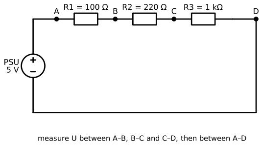
What do we need?
- 1x 100 Ω, 1x 220 Ω, 1x 1 kΩ resistor
- Supply at 5 V, current limit 100 mA
Step 1: Predict
Fill this in before you build anything.
- R total = 100 + 220 + 1000 = ... Ω
- I = U / R total = ... mA
- U1 = I × 100 Ω = ... V
- U2 = I × 220 Ω = ... V
- U3 = I × 1000 Ω = ... V
Step 2: Build and measure the voltages
Build the circuit on the breadboard. The end of one resistor and the start of the next go into the same column, so they are connected. Use the points A, B, C and D from the drawing.
Meter in V DC: black probe on the right side of a resistor, red probe on the left side.
| Measurement | Predicted (V) | Measured (V) |
|---|---|---|
| U over R1 (A to B) | ||
| U over R2 (B to C) | ||
| U over R3 (C to D) | ||
| U over all three (A to D) | ||
| U1 + U2 + U3 added up |
Do the three voltages add up to the supply voltage? Which resistor takes the biggest share, and why?
Step 3: Is the current really the same everywhere?
Measure the current at three different places in the loop. Each time: voltage down to 0 V, open the circuit at that place, meter in series, voltage back up to 5 V.
| Position of the meter | Measured current (mA) |
|---|---|
| Between + rail and R1 | |
| Between R1 and R2 | |
| Between R3 and − rail |
What do you conclude?
Step 4: Measure the total resistance
Turn the voltage down to 0 V and pull the wire that goes to the + rail out of the breadboard. The terminals of this supply stay live, so the wire really has to come out. Meter in Ω mode, probes on A and D.
| Quantity | Calculated (Ω) | Measured (Ω) |
|---|---|---|
| R total of the three resistors in series |
2.8 Parallel circuit
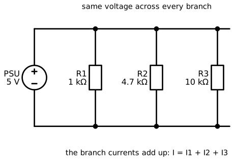
What do we need?
- 1x 1 kΩ, 1x 4,7 kΩ, 1x 10 kΩ resistor
- Supply at 5 V, current limit 100 mA
Step 1: Predict
- I1 = 5 V / 1000 Ω = ... mA
- I2 = 5 V / 4700 Ω = ... mA
- I3 = 5 V / 10000 Ω = ... mA
- I total = I1 + I2 + I3 = ... mA
- R total = U / I total = ... Ω
Step 2: Build and measure
Place the three resistors between the + rail and the − rail, each one in its own pair of columns. Measure the voltage over each resistor, then the current through each branch.
To measure a branch current: voltage down to 0 V, lift the leg of that resistor out of the + rail, put the meter between the rail and the free leg, voltage back up to 5 V.
| Measurement | Predicted | Measured |
|---|---|---|
| U over R1 | ||
| U over R2 | ||
| U over R3 | ||
| I through R1 | ||
| I through R2 | ||
| I through R3 | ||
| I total (from the supply display) |
Take a picture of the finished parallel circuit.
Step 3: Total resistance
Voltage down to 0 V, pull the wire to the + rail out of the breadboard, meter in Ω mode across the whole group.
| Quantity | Calculated (Ω) | Measured (Ω) |
|---|---|---|
| R total of the three resistors in parallel |
The total resistance is smaller than the smallest resistor in the group. Explain in your own words why that makes sense.
2.9 Mixed circuit
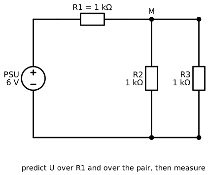
What do we need?
- 3x 1 kΩ resistor
- Supply at 6 V, current limit 100 mA
Step 1: Predict, step by step
- R2 and R3 are in parallel: R23 = ... Ω
- R1 is in series with R23: R total = ... Ω
- I total = 6 V / R total = ... mA
- U over R1 = I total × 1000 Ω = ... V
- U over the parallel pair = 6 V − U over R1 = ... V
- I through R2 = ... mA and I through R3 = ... mA
Step 2: Build and measure
| Measurement | Predicted | Measured |
|---|---|---|
| U over R1 | ||
| U over the parallel pair (node M to − rail) | ||
| I total | ||
| I through R2 | ||
| I through R3 | ||
| R total (voltage at 0 V, wire removed) |
Take a picture of your mixed circuit.
Compare your predictions with your measurements. Where is the difference the biggest, and what could explain it?
2.10 Power, heat and the current limit
Everything you built so far used a few milliamps. Now you find out what happens when you ask a small resistor for real current.
What do we need?
- 1x 100 Ω resistor
- Supply, multimeter
Step 1: Calculate before you build
A 100 Ω resistor on 5 V:
- I = U / R = ... mA
- P = U × I = ... W
The resistors in your kit are rated 0,25 W.
Is this circuit inside the rating, exactly on it, or over it? And what would the power be at 10 V?
Do not go over the rating
Build this circuit at 5 V only. Your calculation above tells you what 10 V would ask from this resistor, and it is far more than the resistor can get rid of: it discolours, it smells, and it can burn your fingers. If a calculation ever lands above 0,25 W, you change the circuit, not the supply.
Step 2: Build it and feel it
- Set the current limit to 100 mA and the voltage to 5 V.
- Connect the 100 Ω resistor between the rails.
- Measure the current. Compare it with your calculation.
- Leave it on for one minute, then briefly touch the body of the resistor with a fingertip.
| Quantity | Calculated | Measured |
|---|---|---|
| I through the 100 Ω resistor | ||
| P dissipated |
What did you feel? Where does that energy come from?
Step 3: See the current limit in action
Now you make the supply refuse.
- Set the current limit to 20 mA, with the same short-circuit method as in step 2.1.
- Remove the short and set the voltage to 5 V.
- Connect the same 100 Ω resistor.
- Read the voltage and the current on the display, and check which indicator is lit: CV or CC.
| Reading | Value |
|---|---|
| Voltage on the display | |
| Current on the display | |
| CV or CC? |
The circuit wanted 50 mA but only gets 20 mA. Use Ohm's law to explain the voltage you see on the display.
Take a picture of the display in CC mode with the resistor connected.
When you are done, set the current limit back to 100 mA.
2.11 Extra: the potentiometer
Steps 2.11 to 2.13 are optional and are not graded.
They are here for students who finish early, and they are a preview of the next labs.
A potentiometer is a resistor with a sliding contact. Turning the knob moves the contact, and that changes the voltage you get out of it.
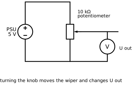
Step 1: Measure it without power
Voltage down to 0 V, potentiometer loose on the table, meter in Ω mode.
| Between which pins | Knob fully left | Knob in the middle | Knob fully right |
|---|---|---|---|
| Outer pin 1 to outer pin 3 | |||
| Outer pin 1 to the middle pin | |||
| Middle pin to outer pin 3 |
Look at the last two rows. What do they add up to, at every knob position?
Step 2: Use it as an adjustable voltage
Connect the two outer pins to the + rail and the − rail, and measure the voltage between the middle pin and the − rail.
| Knob position | U out (V) |
|---|---|
| Fully left | |
| Quarter | |
| Middle | |
| Fully right |
2.12 Extra: a light sensor
An LDR (light dependent resistor) is a resistor whose value changes with the light that falls on it. Combined with a fixed resistor it turns light into a voltage, and a voltage is exactly what a microcontroller can read.

Step 1: The LDR on its own
Meter in Ω mode, LDR loose on the table.
| Situation | Resistance |
|---|---|
| Covered with your hand | |
| Normal room light | |
| Phone torch straight on it |
Step 2: The LDR in a divider
Build the divider with a 10 kΩ resistor and measure the voltage at the middle point.
| Situation | U out (V) |
|---|---|
| Covered with your hand | |
| Normal room light | |
| Phone torch straight on it |
In which situation is U out the highest? Explain it with what you learned about series circuits.
2.13 Extra: an LED is not a resistor
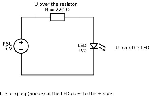
What do we need? 1x red LED, 1x 220 Ω resistor, 1x 1 kΩ resistor.
Build the circuit at 5 V. The long leg of the LED (the anode) goes to the + side. If the LED stays dark, turn it around.
| Measurement | With 220 Ω | With 1 kΩ |
|---|---|---|
| U over the resistor | ||
| U over the LED | ||
| I = U over the resistor / R | ||
| Brightness (dim, normal, bright) |
The voltage over the LED barely changes, even though the current changes a lot. What does that tell you about Ohm's law and LEDs?
3. Reflection
Write a short reflection of approximately half a page (font: Arial 9.5). Answer the following questions in your own words.
What did you learn?
Which concepts from the theory lesson did you recognise in the lab? Give a concrete example from your own measurements.
What was difficult?
Which step gave you the most trouble? How did you solve it?
Measuring versus calculating
Your measurements were never exactly equal to your calculations. Name two causes, and say which one you think had the biggest effect.
Connection to IoT
Later in this course you will connect sensors to a microcontroller. Why does a microcontroller need a circuit like the divider in step 2.12, instead of reading the sensor directly?