
Lab 2: Diodes
1. Assignment description
In lab 1 you worked with a voltage that stayed put. In this lab the voltage moves, and a moving voltage needs two new instruments: the function generator to make it, and the oscilloscope to see it. Once you can drive and read those, you build the circuit that sits inside every power supply in the building: a bridge rectifier.
The order is deliberate. First the instruments, then one diode, then four.
What we expect:
- Every measurement table filled in, with units
- Every resistor you use calculated first, not guessed
- Photos of your circuits, and screenshots or photos of the scope screen where indicated
- A short reflection of approximately half a page in Chapter 3
Planning
| When | Steps | What you do |
|---|---|---|
| Theory lesson (last 1,5 h) | 2.1 to 2.4 | Function generator, oscilloscope, reading a signal off the screen, testing diodes and LEDs |
| Lab session (3 h) | 2.5 to 2.9 | LED with a calculated resistor, half wave rectifier, bridge rectifier, smoothing capacitor, LED on the output |
| If you finish early | 2.10 to 2.12 | RGB LED, ripple against load, other waveforms. Not graded |
What do we need for the whole lab?
From your own kit:
- 1x breadboard and jumper wires
- Resistors: 100 Ω, 220 Ω, 1 kΩ, 4,7 kΩ, 10 kΩ
- 2x red LED, 1x RGB LED
- 1x 1 µF capacitor
From the lab room:
- 1x bench power supply, 1x multimeter with test leads
- 1x function generator with a BNC test lead (crocodile clips)
- 1x oscilloscope with a ×10 probe
- 4x diode 1N4148 or 1N4007 (you get these from the teacher, they are not in your kit)
- 1x electrolytic capacitor 100 µF, 25 V or higher
Safety rules for this lab
- A scope ground clip may only touch the ground of the function generator. Step 2.7 explains why. This is the one rule in this lab that can damage equipment.
- The electrolytic capacitor has a polarity. The stripe marks the − leg. Wrong way round means heat, smell and a bang.
- An LED never goes into a circuit without a series resistor, not even for a quick test.
- On the bench supply, remember from lab 1: there is no output button, so switching off means turning the voltage down to 0 V and pulling the wire out of the + rail.
- Everything in this lab runs on a few volts from an instrument. Mains voltage is never part of the exercise.
2. Lab
2.1 The function generator
A bench supply makes one fixed voltage. A function generator makes a voltage that changes shape over time: a sine, a square or a triangle, at a frequency and an amplitude you choose. It is your AC source for the upcoming labs.
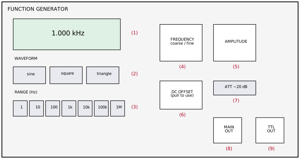
| Nr | Control | What it does |
|---|---|---|
| 1 | Display | Shows the frequency it is putting out. It does not show the amplitude |
| 2 | Waveform | Sine, square or triangle |
| 3 | Range | Multiplier for the frequency dial. Pick the range first, then turn the dial |
| 4 | FREQUENCY dial | Sets the frequency inside the chosen range, coarse and fine |
| 5 | AMPLITUDE | Sets how big the signal is. No readout, so you set it with the scope |
| 6 | DC OFFSET | Shifts the whole signal up or down. Stays off in this lab |
| 7 | ATT −20 dB | Attenuator, makes the output ten times smaller. Stays out in this lab |
| 8 | MAIN OUT | The BNC output you use. The outer ring of the BNC is ground |
| 9 | TTL OUT | A fixed 5 V square wave for digital circuits. Not used today |
Step 1: Find the controls on your own unit
Your generator may put these in a different order or give them slightly different names. Before you switch anything on, find each of the nine controls and write down where it is.
| Nr | Control | Where is it on your unit? |
|---|---|---|
| 1 | Frequency display | |
| 2 | Waveform selection | |
| 3 | Range | |
| 4 | Frequency dial | |
| 5 | Amplitude | |
| 6 | DC offset | |
| 7 | Attenuator | |
| 8 | Main output |
Step 2: Make your first signal
- Switch the generator on.
- Choose sine.
- Choose the range that contains 1 kHz and turn the dial until the display reads 1,000 kHz as closely as you can.
- Turn the AMPLITUDE knob to about the middle.
- Make sure DC OFFSET is off and the attenuator is out.
Look at the display. Which of the two settings that matter, frequency and amplitude, can you actually read on this instrument?
2.2 The oscilloscope
The multimeter gives you one number per measurement. The oscilloscope draws the shape of a voltage against time, which is the only way to see what a diode is really doing to a signal.
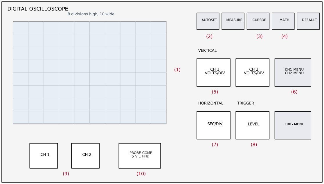
| Nr | Control | What it does |
|---|---|---|
| 1 | Screen | A grid of divisions: 10 wide, 8 high. Everything is read in divisions |
| 2 | AUTOSET | The scope tries to find a stable picture by itself. Your rescue button |
| 3 | CURSOR | Two lines you move over the trace to measure a distance yourself |
| 4 | MATH | Calculates with the channels, for example CH1 − CH2. You need this in step 2.7 |
| 5 | VOLTS/DIV | How many volts one division is worth, per channel. The vertical zoom |
| 6 | CH1 / CH2 MENU | Switches a channel on or off, sets coupling and probe factor |
| 7 | SEC/DIV | How much time one division is worth. The horizontal zoom |
| 8 | TRIGGER | Decides where the scope starts drawing, so a repeating signal stands still |
| 9 | CH1 and CH2 inputs | BNC connectors for the probes |
| 10 | PROBE COMP | A built-in test signal: a 5 V square wave at 1 kHz |
Step 1: The probe
A scope probe is not a piece of wire. It contains a resistor network that divides the signal by ten, which is why it is called a ×10 probe. The scope has to be told about that, otherwise every voltage you read is ten times too small.
- Plug the probe into CH1.
- Check the switch on the probe body: set it to 10X.
- Press CH1 MENU and set the probe factor in the menu to 10X as well.
Step 2: Compensate the probe
Clip the probe tip onto the PROBE COMP terminal and the ground clip onto the ground tab next to it. Press AUTOSET. You should see a square wave.
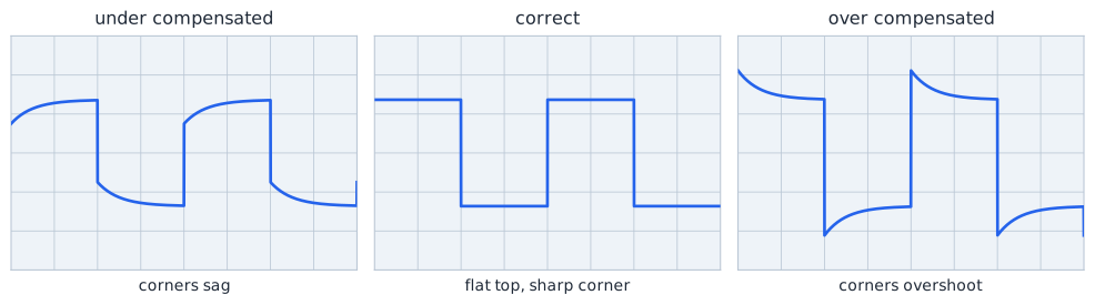
If the corners are not square, turn the small trimmer screw on the probe body with a small screwdriver until the top of the square wave is flat.
Take a picture of your screen after compensating.
Step 3: Read the screen without the automatic measurements
Everything on a scope screen is counted in divisions. The two knobs tell you what one division is worth.
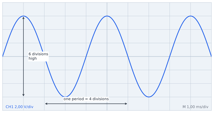
In the picture above:
- The wave is 6 divisions high and CH1 is set to 2 V/div, so U peak-to-peak = 6 × 2 = 12 V
- One period is 4 divisions wide and the scope is set to 1 ms/div, so T = 4 × 1 = 4 ms and f = 1 / 0,004 = 250 Hz
Now do the same with the PROBE COMP signal on your own screen.
| Reading | Your answer |
|---|---|
| VOLTS/DIV setting | |
| Height of the square wave in divisions | |
| U peak-to-peak (calculated) | |
| SEC/DIV setting | |
| One period in divisions | |
| Period T (calculated) | |
| Frequency f (calculated) |
The PROBE COMP output is specified as 5 V at 1 kHz. Do your calculated values match? If not, check the probe factor first.
2.3 The generator and the scope together
Now connect the two instruments and check whether the generator does what it claims.
Connect: the BNC lead from MAIN OUT of the generator to the breadboard, black clip to the − rail, red clip to the + rail. Put the CH1 probe tip on the + rail and its ground clip on the − rail.
Step 1: Set an exact amplitude
The generator cannot show you its amplitude, so use the scope for it. Set a sine of 1 kHz and turn the AMPLITUDE knob until the scope shows exactly 6 V peak-to-peak.
Use MEASURE to help: press MEASURE, choose CH1 and the measurement Pk-Pk, and a second one for Freq.
| Quantity | Read from the divisions | Read with MEASURE |
|---|---|---|
| U peak-to-peak | ||
| U peak | ||
| Period T | ||
| Frequency f |
Step 2: Three frequencies
Keep the amplitude at 6 Vpp and set the generator to each frequency below. Each time, adjust SEC/DIV so that you see two or three periods, and read the period off the screen.
| Generator display | SEC/DIV you used | Period from the screen | Frequency you calculate |
|---|---|---|---|
| 100 Hz | |||
| 1 kHz | |||
| 10 kHz |
Step 3: The same signal on the multimeter
Set the generator to 100 Hz and 6 Vpp. Measure the same signal with the multimeter in V AC mode (probes on the same two rails).
| Measurement | Value |
|---|---|
| U peak-to-peak on the scope | |
| U peak (calculated) | |
| U RMS you expect (U peak × 0,707) | |
| U AC on the multimeter |
The scope and the multimeter show different numbers for the same signal. Is one of them wrong? Explain what each instrument is telling you.
Your meter has a frequency limit
A cheap multimeter is built to measure the mains at 50 Hz. Feed it 10 kHz and the reading quietly drops, even though the signal has not changed. Check the manual of your meter for the frequency range of its AC ranges before you trust an AC reading.
2.4 Getting to know the diode
Before you build anything, get to know the component itself.
What do we need? 2x diode, 1x red LED, 1x green or yellow LED, 1x blue or white LED (or the RGB LED from your kit), 1x 1 kΩ resistor.
Step 1: Which side is which?
Look at the diode. One end has a printed ring around the body. That ring marks the cathode, the side the current comes out of. On an LED the marking is different: the short leg is the cathode, and the plastic rim is flattened on that side.
Step 2: The diode test on the multimeter
Your multimeter has a diode symbol on the rotary switch. In that position the meter pushes a small current through the component and shows you the voltage it needs.
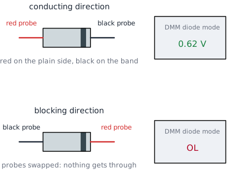
Test each component in both directions and write down what the display shows. "OL" means no current gets through.
| Component | Red probe on the plain side | Red probe on the ring / short leg |
|---|---|---|
| Diode 1 | ||
| Diode 2 | ||
| Red LED | ||
| Green or yellow LED | ||
| Blue or white LED | ||
| 1 kΩ resistor |
Which components lit up faintly while you were testing them, and which one refused to show a value at all? Use the forward voltage table from the theory to explain why.
Why does the resistor behave differently from all the others in this test?
2.5 An LED with a resistor you calculate yourself
This is the calculation you will repeat for the rest of your career, so do it properly once.
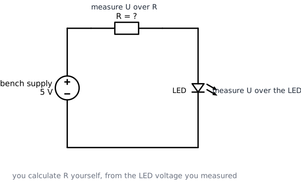
What do we need? 1x red LED, resistors from your kit, bench supply, multimeter.
Step 1: Calculate
You want 10 mA through a red LED on a 5 V supply. Use the forward voltage you measured yourself in step 2.4, or 2,0 V if your measurement looked odd.
Then pick the closest value above your result from your kit (100 Ω, 220 Ω, 1 kΩ, 4,7 kΩ, 10 kΩ) and calculate what current that resistor will really give.
Step 2: Build and measure
- Voltage to 0 V. Build the circuit: + rail, resistor, LED (long leg towards the resistor), − rail.
- Set the supply to 5 V with the current limit at 100 mA.
- Measure and fill in the table.
| Quantity | Predicted | Measured |
|---|---|---|
| U over the resistor | ||
| U over the LED | ||
| U over R + U over LED | ||
| I through the circuit (calculated from U over R) |
Take a picture of the working circuit.
Step 3: Change the resistor
Swap your resistor for a 1 kΩ and repeat.
| Quantity | Calculated | Measured |
|---|---|---|
| U over the LED | ||
| I through the circuit | ||
| Brightness (dim, normal, bright) |
The LED voltage barely moved while the current changed a lot. Which component in this circuit decides the current, and which one decides the voltage?
Compare the LED voltage you measured here with the value the multimeter showed in diode mode in step 2.4. Are they the same? Why not?
2.6 Half wave rectifier
One diode, one resistor, and your first rectifier.
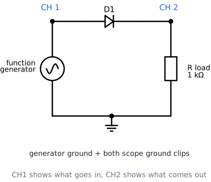
What do we need? 1x diode, 1x 1 kΩ resistor, function generator, scope with two probes.
Step 1: Build it
- Generator to the breadboard: black clip to the − rail, red clip to a free column. Call that column the input.
- Diode from the input column to a second column, with the ring pointing away from the input.
- Resistor from that second column to the − rail.
- CH1 probe tip on the input column, CH2 probe tip on the second column.
- Both ground clips on the − rail, which is also the generator ground.
- Generator: sine, 100 Hz, amplitude to maximum.
Press AUTOSET, then set both channels to the same VOLTS/DIV so you can compare them fairly.
Step 2: Look and measure
| Measurement | Value |
|---|---|
| U peak of the input (CH1) | |
| U peak of the output (CH2) | |
| Difference between the two | |
| What CH2 does during the negative half of CH1 |
Take a picture of the screen with both traces visible.
Step 3: What does the multimeter make of it?
Measure the output with the multimeter in V DC mode, across the 1 kΩ resistor.
| Measurement | Value |
|---|---|
| U DC on the multimeter | |
| 0,318 × U peak of the output (calculated) |
Step 4: Turn the amplitude down
Reduce the generator amplitude until the input is only about 2 V peak-to-peak, and watch CH2.
What happens to the output, and why does the diode suddenly ruin so much more of the signal?
Turn the amplitude back to maximum before you continue.
2.7 Bridge rectifier without a capacitor
Four diodes, and both halves of the wave reach the load. This is the core circuit of this lab.
First read this, before you clip anything on
The ground clip of a scope probe is connected to the metal case of the scope, which is connected to the earth pin of its power plug. The ground of the function generator is earthed in exactly the same way. All those grounds are one and the same point, even though they are separate crocodile clips.
In the circuits so far that was harmless, because the generator ground and the load both sat on the − rail. In a bridge rectifier neither output rail is at ground, and clipping a probe ground onto one of them short circuits a diode:
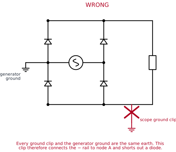
Rule for the rest of this lab: both ground clips go to the generator ground, and nowhere else. To see the voltage across the load you use two probes and let the scope subtract them.
Step 1: Build the bridge
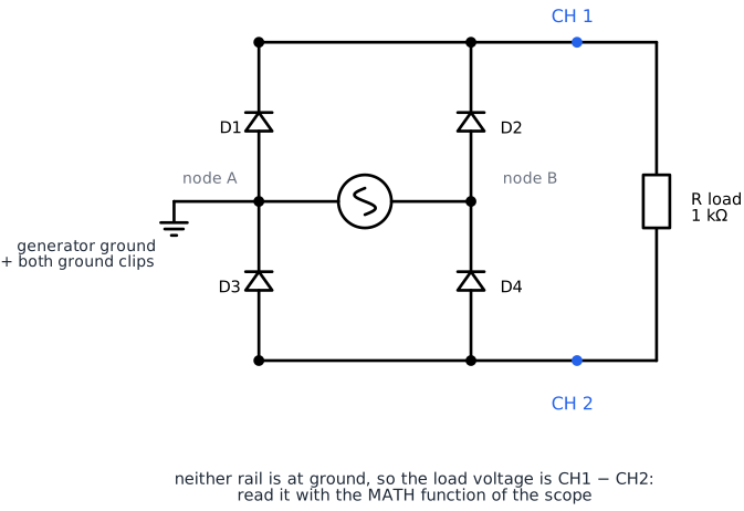
Use four columns on your breadboard: node A, node B, the + rail and the − rail. Then place the four diodes exactly as in this table. Watch the ring on every single one.
| Component | From | To | Ring (cathode) side |
|---|---|---|---|
| D1 | node A | + rail | + rail |
| D2 | node B | + rail | + rail |
| D3 | − rail | node A | node A |
| D4 | − rail | node B | node B |
| Generator black clip | node A | ||
| Generator red clip | node B | ||
| R load 1 kΩ | + rail | − rail |
All four rings point towards the + rail, or away from the − rail. If one of them points the other way, the bridge does not work.
Step 2: Measure with MATH
- CH1 probe tip on the + rail, CH2 probe tip on the − rail.
- Both ground clips on node A (the generator ground).
- Set CH1 and CH2 to the same VOLTS/DIV. The subtraction is only meaningful if both channels use the same scale.
- Press MATH and select CH1 − CH2.
The MATH trace is the voltage across your load.
| Measurement | Value |
|---|---|
| U peak of the generator (CH1 to CH2 before the bridge, or from step 2.6) | |
| U peak of the MATH trace | |
| Difference between the two | |
| Number of bumps you count in one period of the input | |
| U DC across the load on the multimeter | |
| 0,637 × U peak of the output (calculated) |
Take a picture of the screen with the MATH trace.
In the half wave circuit you lost about 0,7 V. Here you lose about twice as much. Explain where the second 0,7 V goes.
Compare the DC voltage on the multimeter with the one you measured in step 2.6. Which rectifier delivers more, and roughly by how much?
2.8 The smoothing capacitor
The output is DC, but it is still a row of bumps. Time to flatten it.
What do we need? the circuit from 2.7, plus the 100 µF electrolytic capacitor and the 1 µF capacitor from your kit.
Step 1: Add the capacitor
- Turn the generator amplitude down first.
- Place the 100 µF capacitor between the + rail and the − rail, + leg on the + rail. Check the stripe.
- Turn the amplitude back up and look at the MATH trace.
| Measurement | Without capacitor | With 100 µF |
|---|---|---|
| Shape of the MATH trace (describe in a few words) | ||
| Highest point of the trace | ||
| Lowest point of the trace | ||
| U DC on the multimeter |
Use CURSOR on the MATH trace to measure the top and the bottom of the remaining ripple accurately.
| Quantity | Value |
|---|---|
| Ripple ΔU measured with the cursors |
Step 2: Check it against the formula
The theory says:
Calculate the load current from your own measurement (), take Hz, and compare.
Step 3: A smaller capacitor
Replace the 100 µF with the 1 µF from your kit and look again.
| Measurement | With 1 µF |
|---|---|
| Shape of the trace | |
| Ripple ΔU | |
| U DC on the multimeter |
Name two changes to this circuit that would make the ripple smaller, and one change that would make it worse.
Put the 100 µF back for the next step.
2.9 An LED on the output of your power supply
You have built a small DC supply. Now use it.
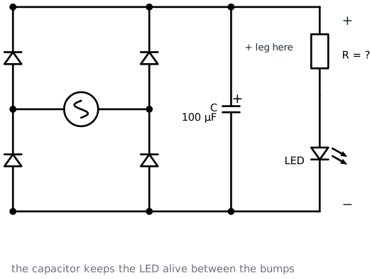
Step 1: Calculate the resistor again
Take the DC voltage you measured in step 2.8 with the 100 µF capacitor as your supply voltage, and calculate the series resistor for a red LED at 10 mA. Pick the nearest value above it from your kit.
Step 2: Build and measure
Replace the 1 kΩ load with your resistor and the LED in series, the LED's long leg towards the + rail.
| Measurement | Predicted | Measured |
|---|---|---|
| U over the resistor | ||
| U over the LED | ||
| I through the LED | ||
| U DC across the whole load |
Take a picture of the LED burning on your own rectifier.
Step 3: Slow it all down
Now make the rectifier visible with your own eyes instead of the scope.
- Take the capacitor out of the circuit.
- Set the generator to 2 Hz.
- Watch the LED and count.
| Situation | Flashes per second you count | Describe what you see |
|---|---|---|
| Bridge, no capacitor, 2 Hz | ||
| Half wave (pull out D2 and D3), no capacitor, 2 Hz | ||
| Bridge with 100 µF back in, 2 Hz |
The bridge flashes twice as often as the half wave circuit at the same generator frequency. Explain why in one sentence.
Step 4: Find your own flicker limit
Put the bridge back together (all four diodes, no capacitor) and slowly raise the generator frequency until you can no longer see the LED flicker.
| Quantity | Value |
|---|---|
| Frequency where the flicker disappears for you | |
| Frequency where your neighbour stops seeing it |
The mains runs at 50 Hz and a lamp on a bridge rectifier flickers at 100 Hz. Does that match what you just measured?
2.10 Extra: the RGB LED
Steps 2.10 to 2.12 are optional and are not graded.
The RGB LED in your kit is three LEDs in one package with one shared leg. Because the three colours have different forward voltages, they need three different series resistors for the same brightness.
- Find out whether yours is a common cathode or a common anode type, using the diode mode of your multimeter.
- Measure the forward voltage of each of the three colours.
- Calculate a series resistor for each colour, for 10 mA on 5 V.
- Build it and check the current in each branch.
| Colour | U forward measured | R calculated | R used | I measured |
|---|---|---|---|---|
| Red | ||||
| Green | ||||
| Blue |
Which colour needed the smallest resistor, and does that match the theory?
2.11 Extra: ripple against load current
Go back to the bridge with the 100 µF capacitor and try four different load resistors. Each time, measure the DC voltage and the ripple with the cursors.
| R load | U DC measured | I load (calculated) | Ripple measured | Ripple from the formula |
|---|---|---|---|---|
| 10 kΩ | ||||
| 4,7 kΩ | ||||
| 1 kΩ | ||||
| 220 Ω |
Draw a small graph of the ripple against the load current. Does the measurement follow the formula?
2.12 Extra: other waveforms
Keep the bridge and the 1 kΩ load, remove the capacitor, and switch the generator between sine, square and triangle at 100 Hz.
| Waveform in | Sketch or describe the MATH trace | U DC on the multimeter |
|---|---|---|
| Sine | ||
| Square | ||
| Triangle |
Which waveform gives the highest DC voltage for the same peak value, and can you explain why?
3. Reflection
Write a short reflection of approximately half a page (font: Arial 9.5). Answer the following questions in your own words.
What did you learn?
Which concepts from the theory lesson did you recognise in the lab? Give a concrete example from your own measurements.
What was difficult?
Which step gave you the most trouble? How did you solve it?
The ground rule
Explain in your own words, as if to a fellow student who missed this lab, why a scope ground clip may not be put anywhere you like, and how you measured the load voltage instead.
Connection to IoT
Open the charger of your phone or your laptop and look at the label: it takes 230 V AC and gives a few volts DC. Name the parts of the circuit you built today that must be inside it, and name one thing that is in there which you have not built yet.