
Filters
A signal almost never arrives on its own. A microphone picks up your voice and the hum of the mains. A temperature sensor gives a slow reading with fast noise spikes on top. A radio antenna receives every station at once.
In all of those cases you want to keep one part of the signal and throw the rest away. The part you keep and the part you throw away differ in frequency, and a circuit that separates them is called a filter.

There are four types, and their names say exactly what they do. This lesson covers the simplest version of each, built from one resistor and one capacitor. That version is called first order, and it is all you need for now.
The Capacitor Decides
You already know from lesson 2 that a capacitor blocks a steady DC voltage and lets changes through. A filter is built on that one sentence, so it is worth making it precise.
The opposition a capacitor offers is called reactance, written . Like resistance it is measured in ohms, but it is not a fixed value: it depends on the frequency.
with in hertz and in farad.
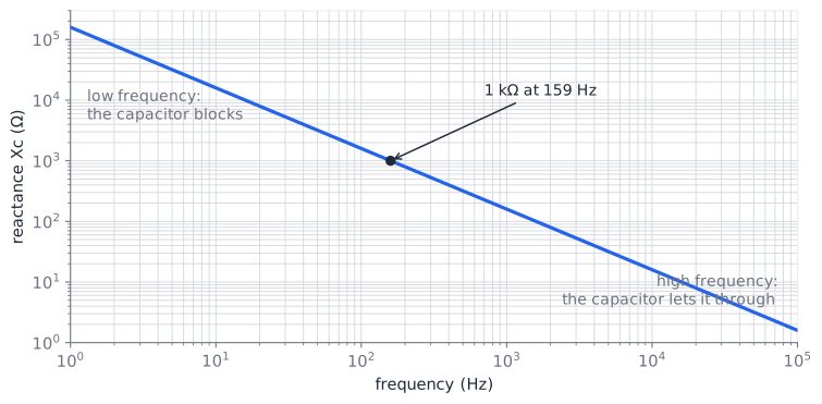
Read the formula, not the graph, first: the frequency sits in the bottom of the fraction. So
- low frequency, high reactance. At 0 Hz (pure DC) the reactance is infinite: the capacitor is an open circuit.
- high frequency, low reactance. Fast signals hardly notice the capacitor at all.
Example: one capacitor, two frequencies
A 1 µF capacitor at 50 Hz and at 5 kHz:
The same component acts like a 3,2 kΩ resistor for the slow signal and like a 32 Ω resistor for the fast one. That is the whole trick behind every filter in this lesson.
The Low Pass Filter
Put a resistor and a capacitor in series and take the output across the capacitor.
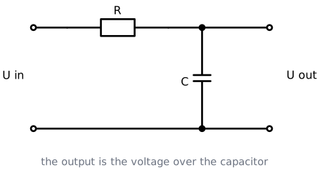
This is a voltage divider, exactly like in lesson 1, except that the bottom half changes value with frequency:
- Low frequency: is large compared to R, so the capacitor takes almost the whole input voltage. The output is nearly equal to the input.
- High frequency: is small, so the capacitor takes almost nothing. The output collapses.
Low frequencies pass, high frequencies do not. Hence the name.
The cut-off frequency
Somewhere in between sits the frequency where is exactly equal to R. That point is called the cut-off frequency:
At that frequency the output is 0,707 times the input. Not half, because the resistor and the capacitor do not simply add up: the capacitor also shifts the signal in time, and the two effects combine at an angle. You do not need that calculation, but you do need the number 0,707, because that is where the filter is officially "cut off".
Reading the graph: decibels
Filter behaviour is drawn on a graph with the frequency on a logarithmic axis, so every step to the right multiplies the frequency by ten. Such a step is called a decade.
The vertical axis compares the output with the input in decibels (dB):
You only need to recognise a handful of values:
| Output compared to input | In decibels | Meaning |
|---|---|---|
| 1 (unchanged) | 0 dB | passes through untouched |
| 0,707 | −3 dB | the cut-off point |
| 0,5 (half) | −6 dB | |
| 0,1 (a tenth) | −20 dB | |
| 0,01 (a hundredth) | −40 dB |
The response of a low pass filter
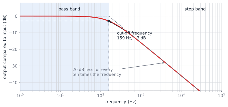
The graph shows the filter of the example below: R = 1 kΩ and C = 1 µF, so = 159 Hz.
- Left of the cut-off is the pass band. The line is flat at 0 dB: whatever goes in comes out.
- Right of the cut-off is the stop band. The line falls by 20 dB per decade, so ten times the frequency means a tenth of the output.
- The two dashed straight lines are how you sketch this by hand: flat until , then downhill. The real curve only differs near the corner.
The same thing in the time domain, with an actual signal going through:
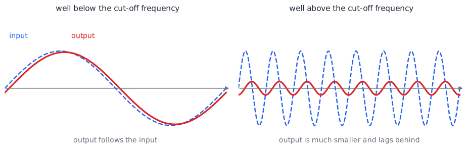
Notice the second panel: besides being smaller, the output also lags behind the input. A filter always shifts the signal in time as well. At the cut-off frequency that shift is 45 degrees. It matters in audio and in control systems, and for now it is enough to know it happens.
Example 1: What is the cut-off frequency?
R = 1 kΩ and C = 1 µF:
A 50 Hz signal is well inside the pass band and comes through almost untouched. A 5 kHz signal is more than a decade above the cut-off and is heavily reduced.
Example 2: Choosing a part for a given cut-off
You want a low pass at 1 kHz and you have decided to use R = 1 kΩ. Which capacitor?
Rearrange the formula:
The nearest standard value is 150 nF, which gives a cut-off of 1,06 kHz. Close enough for nearly every job.
The High Pass Filter
Swap the two components. Same resistor, same capacitor, but now the output is taken across the resistor.
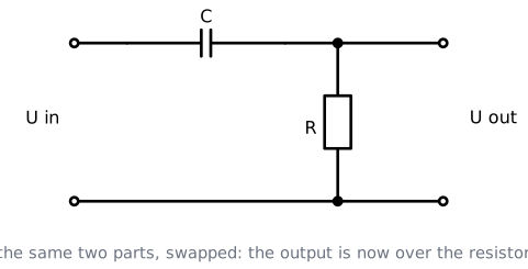
The reasoning is the mirror image:
- Low frequency: is large, so the capacitor keeps the voltage for itself and the resistor gets almost nothing. The output is small.
- High frequency: is small, so the signal passes the capacitor easily and appears across the resistor.
The cut-off frequency is calculated with exactly the same formula:
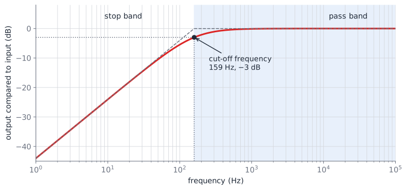
Same components, same cut-off frequency, opposite behaviour. The slope in the stop band is again 20 dB per decade, now going the other way.
You have already used one
The capacitor between two audio stages, the one that "removes the DC" and passes the music, is a high pass filter. So is the capacitor in front of the AC input of your multimeter.
The Band Pass Filter
To keep only a band of frequencies, you throw away the low ones and the high ones. Put a high pass and a low pass one after the other.
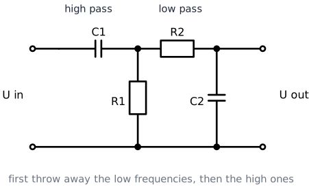
Each section keeps its own formula:
- The high pass section (C1 and R1) sets the lower cut-off frequency
- The low pass section (R2 and C2) sets the upper cut-off frequency
The distance between the two is the bandwidth.
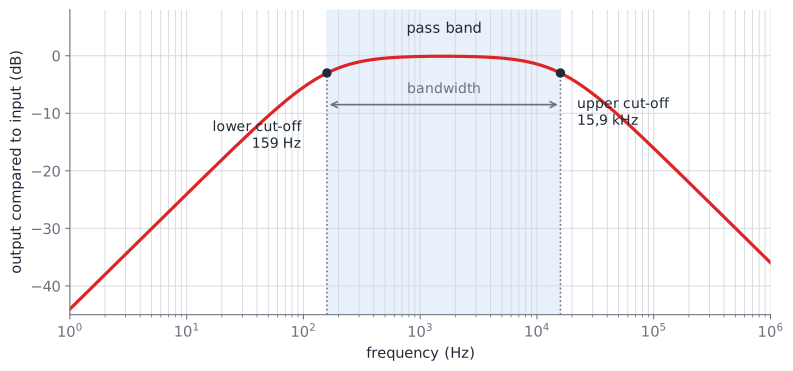
Example: a band pass for speech
Human speech sits roughly between 300 Hz and 3 kHz. Everything below is rumble, everything above is hiss. With R1 = R2 = 1 kΩ:
Order matters for the two sections only in the sense that the upper cut-off must be higher than the lower one. If you accidentally choose them the other way round, nothing passes at all.
The Band Stop Filter
The last type does the opposite: it lets everything through except one band. It is also called a notch filter, because it cuts a notch out of the response.
You cannot make it by putting a low pass behind a high pass, because then the two sections would block each other's pass band and nothing would come out. Instead you split the signal, filter the two halves separately, and add them back together:
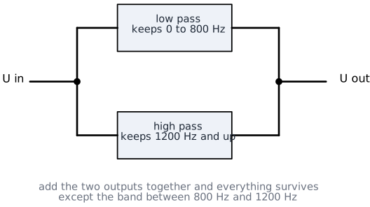
The low pass keeps everything below the notch, the high pass keeps everything above it, and the band in between is in neither path.
Adding two signals together needs an extra component, which is why a real notch filter uses either a special network of resistors and capacitors (a twin-T) or an amplifier. You will meet the amplifier in lesson 4.
The classic use is removing the 50 Hz hum of the mains from a measurement, for example in medical equipment or in an audio recording.
Higher Orders, Briefly
Every filter in this lesson is first order: one resistor and one capacitor, and a slope of 20 dB per decade. That slope is gentle. If your signal sits at 1 kHz and the noise at 2 kHz, a first order filter barely separates them.
Cascading more sections makes the corner sharper:
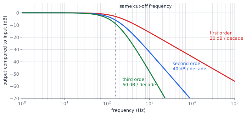
| Order | Sections | Slope | Typical use |
|---|---|---|---|
| First | 1 R and 1 C | 20 dB / decade | smoothing a sensor signal, removing noise, most IoT work |
| Second | 2 | 40 dB / decade | audio crossovers, anti-aliasing in front of an ADC |
| Third and higher | 3 or more | 60 dB / decade and steeper | radio, professional audio, measurement equipment |
You do not have to calculate these
Second and third order filters are named here so that you recognise the words in a datasheet: Butterworth, Chebyshev, Sallen-Key. Designing them is not part of this course, and neither is calculating them. What matters is that you know why they exist: a steeper slope, when a first order filter separates too little.
There is a second reason to go beyond the simple RC circuit. Whatever you connect behind an RC filter draws a little current, and that changes the cut-off frequency of the filter itself. A filter with an amplifier in it (an active filter) does not have that problem. That is one of the things lesson 4 is about.
Where You Meet Filters in IoT
Filters are not an audio topic that you can skip as an embedded developer. You will use them constantly:
- Smoothing a sensor reading. An RC low pass on an analogue sensor output removes noise spikes before the value reaches the ADC.
- In front of every ADC. A converter cannot tell the difference between a fast signal and a slow one that was sampled badly. A low pass in front of it, called an anti-aliasing filter, prevents that.
- Turning PWM into a voltage. A PWM output plus an RC low pass gives you a simple analogue output on a microcontroller that has none.
- Debouncing a push button. A small RC filter across a switch removes the contact bounce that would otherwise be read as ten presses.
- Decoupling capacitors. The 100 nF capacitor next to the supply pin of every chip is a low pass filter that keeps switching noise off the supply rail.
Try it yourself!
Question 1: A low pass filter uses R = 10 kΩ and C = 1 µF. What is the cut-off frequency?
Solution
Very low. This filter passes only slowly changing signals, which is exactly what you want for a temperature sensor.
Question 2: You need a high pass filter with a cut-off frequency of 1 kHz and you have 100 nF capacitors. Which resistor do you use?
Solution
The nearest standard value is 1,5 kΩ, giving a cut-off of 1,06 kHz.
Question 3: A signal of 6 V peak arrives at a low pass filter, at exactly the cut-off frequency. How large is the output?
Solution
Which is the same as saying the filter attenuates by 3 dB at that point.
Question 4: The same low pass filter has a cut-off frequency of 159 Hz. Roughly how much of a 1,59 kHz signal comes through?
Solution
1,59 kHz is exactly one decade above the cut-off frequency. A first order filter loses 20 dB per decade, and 20 dB is a factor of ten.
So about a tenth of the input voltage comes out.
Key Takeaways
A capacitor is a frequency dependent resistance: . Low frequency means high reactance, high frequency means low reactance.
A first order filter is a voltage divider in which one of the two halves changes with frequency.
Low pass: output across the capacitor. High pass: output across the resistor. Same two parts, swapped.
The cut-off frequency is the same formula for both: .
At the cut-off frequency the output is 0,707 of the input, which is −3 dB.
A first order filter falls by 20 dB per decade in the stop band: ten times the frequency, a tenth of the output.
Band pass = high pass followed by low pass. The two cut-off frequencies set the bandwidth.
Band stop keeps everything except one band and needs more than two components to build.
Higher order filters have a steeper slope, 40 dB per decade for second order and 60 for third. You do not have to calculate them.
Glossary: Key Terms and Abbreviations
These are the new terms from this lesson. The terms from lesson 1 and lesson 2 still apply and are not repeated here.
Active filter
A filter that contains an amplifier as well as resistors and capacitors. It does not change its behaviour when a load is connected to it.
Anti-aliasing filter
A low pass filter placed in front of an analogue to digital converter, so that frequencies the converter cannot handle never reach it.
Attenuation
How much a filter reduces a signal, usually expressed in decibels.
Band pass filter
A filter that passes a band of frequencies and blocks everything above and below it.
Band stop filter
A filter that blocks a band of frequencies and passes everything above and below it. Also called a notch filter.
Bandwidth
The distance between the lower and the upper cut-off frequency of a band pass filter, in hertz.
Cut-off frequency (fc)
The frequency at which the output of a filter has fallen to 0,707 of the input, which is −3 dB. Also called the corner frequency. .
Decade
A factor of ten in frequency. From 100 Hz to 1 kHz is one decade.
Decibel (dB)
A logarithmic way of comparing two voltages: . 0 dB is unchanged, −3 dB is 0,707, −20 dB is a tenth.
Filter order
How many resistor and capacitor sections a filter has. Each order adds 20 dB per decade to the slope.
Frequency response
The graph of a filter's output against frequency, with the frequency on a logarithmic axis. Also called a Bode plot.
High pass filter
A filter that passes frequencies above its cut-off frequency and blocks the ones below.
Low pass filter
A filter that passes frequencies below its cut-off frequency and blocks the ones above.
Notch filter
Another name for a band stop filter, especially a narrow one, for example one that removes 50 Hz mains hum.
Pass band
The range of frequencies a filter lets through.
Passive filter
A filter built only from resistors, capacitors and coils, with no amplifier. Every filter in this lesson is passive.
Phase shift
The delay a filter adds to a signal, expressed as an angle. A first order filter shifts by 45 degrees at its cut-off frequency.
Reactance (XC)
The opposition a capacitor offers to an AC signal, in ohms. It depends on the frequency: .
Roll-off
The slope of a filter response in the stop band, in decibels per decade. 20 dB per decade for a first order filter.
Stop band
The range of frequencies a filter blocks.
Extra Resources
- Electronics Tutorials: Passive Low Pass Filter and Passive High Pass Filter, with more worked examples in the same style as this lesson
- Falstad circuit simulator has ready made RC filters under Circuits, Filters. Sweep the frequency and watch the output shrink
- OKAWA RC filter calculator to check your own calculations of R, C and the cut-off frequency