
Diodes
In lesson 1 every component treated current the same in both directions. A resistor does not care which way the electrons travel: turn it around and nothing changes.
The diode is the first component that does care. It lets current pass in one direction and blocks it in the other. That one property is enough to turn the alternating voltage from a wall socket into the steady voltage a microcontroller needs, to protect a circuit against a coil that fights back, to hold a voltage at a fixed value, and to make light.
This lesson builds that up step by step: first what AC actually is, then what happens inside the material, then the diode itself and everything you can build with it.
From AC to DC
Before you can understand why a diode is useful, you need to know what it is being used on.
Two kinds of voltage

DC stands for direct current. The voltage keeps the same value and, more importantly, the same direction. The + terminal stays +, the − terminal stays −. A battery, a USB charger and the bench supply from lab 1 all deliver DC.
AC stands for alternating current. The voltage swings up and down and changes direction over and over again. What was + becomes − a moment later. The socket in the wall delivers AC, and so does the function generator you will use in the lab.
Why does the grid use AC at all?
Because AC can be transformed. A transformer changes 230 V into 12 V (or the other way round) with almost no losses, and it only works on a voltage that keeps changing. High voltage means low current, and low current means thin cables and small losses over long distances. Once the electricity arrives at your device, it is converted back to DC.
The numbers that describe an AC signal
A DC voltage needs one number: 5 V and you know everything. An AC voltage needs more, because it is a shape that repeats.

- Period (T): the time one complete wave takes, in seconds.
- Frequency (f): how many complete waves fit in one second, in hertz (Hz). Frequency and period are each other's opposite:
- Peak value (U peak): the highest voltage the wave reaches, measured from the zero line.
- Peak-to-peak value (U pp): from the lowest point to the highest point. For a sine wave this is simply twice the peak value.
- RMS value (U RMS): the "fair" value, explained below.
The mains in Europe is 230 V at 50 Hz. So one period lasts s = 20 ms, and the voltage changes direction 100 times per second.
RMS: the honest average
An AC voltage is 0 V twice in every period, and its ordinary average over a full period is exactly zero, because the positive half cancels the negative half. Yet a heating element on AC clearly gets hot. So we need a number that says how much work the signal does.
That number is the RMS value (root mean square). The definition is short and useful:
The RMS value of an AC voltage is the DC voltage that would produce the same heat in the same resistor.
For a sine wave the relationship is fixed:
This is why "230 V" from the wall socket actually peaks at V. The 230 V is the RMS value; the insulation of your cable has to survive the 325 V.
When you use RMS values, Ohm's law and the power formulas from lesson 1 keep working exactly as they are:
That is the whole point of RMS: it lets you calculate with AC as if it were DC.
Example 1: From peak to RMS
A function generator is set to a sine wave of 10 V peak. Which RMS voltage would a multimeter in AC mode show?
Example 2: Power in a resistor on AC
That same 10 V peak signal is connected to a 1 kΩ resistor. How much power does the resistor dissipate?
First convert to RMS, then use the formula from lesson 1:
If you had used the peak value by mistake you would have found 100 mW: twice as much. RMS matters.
Try it yourself!
Question 1: A signal has a period of 5 ms. What is its frequency?
Solution
Question 2: An oscilloscope shows a sine wave of 8 V peak-to-peak. What is the peak value, and what is the RMS value?
Solution
Question 3: A transformer is labelled "12 V AC". What is the highest voltage this transformer actually produces?
Solution
The label always gives the RMS value.
A capacitor connected behind this transformer will be charged to roughly 17 V, not 12 V. Choose its voltage rating accordingly.
Conductors, Semiconductors and Insulators
A diode is not built from wire and plastic. It is built from a material that sits exactly in between: a semiconductor. To see why that matters, look at what makes a material conduct in the first place.
It is all about the outer electrons
Every atom has electrons in shells around it. Only the electrons in the outermost shell, the valence electrons, take part in conduction. What counts is how tightly the material holds on to them.
| Material type | Valence electrons | Holding on to them | Example |
|---|---|---|---|
| Conductor | 1 to 3 | very loosely | copper, silver, gold, aluminium |
| Semiconductor | 4 | in between | silicon, germanium |
| Insulator | 8 (full shell) | very tightly | glass, rubber, most plastics, dry air |
A copper atom has one lonely valence electron that is barely attached. In a piece of copper those electrons drift around freely, so the tiniest voltage already produces current.
Rubber has a full outer shell. Its electrons have nowhere to go and nothing to gain, so almost no current flows, even at high voltage.
Silicon has four. That is the awkward middle: not free, not locked. Silicon atoms bind to each other by sharing those four electrons, which leaves the material in a strange state, it conducts a bit, badly, and its behaviour can be changed on purpose. That last part is what makes electronics possible.
The same story in energy
Physicists draw this as two bands of energy. Electrons sitting in the valence band are bound to their atom. Electrons that make it up into the conduction band are free to move and can carry current. In between sits a gap that an electron has to jump over.
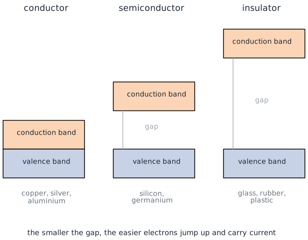
- Conductor: the bands touch or overlap. There is no jump to make, so there are always free electrons.
- Insulator: the gap is huge. Nothing gets across unless you apply a destructive voltage.
- Semiconductor: the gap is small. At room temperature a few electrons make the jump, which is why a semiconductor conducts slightly, and why it conducts better when it gets hotter. That is the opposite of a metal, where higher temperature means more resistance.
Doping: making silicon useful
Pure silicon is not very interesting. It becomes useful when we deliberately add a tiny amount of another element, roughly one foreign atom per ten million silicon atoms. That is called doping.
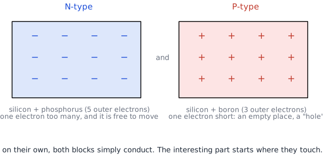
N-type (N for negative): we add an element with five valence electrons, such as phosphorus, arsenic or antimony. Four of them bond with the neighbouring silicon atoms. The fifth has no partner and wanders off: a free electron. N-type silicon has a surplus of free electrons.
P-type (P for positive): we add an element with three valence electrons, such as boron, gallium or indium. Now one bond is missing an electron. That empty spot is called a hole. A neighbouring electron can hop into the hole, which leaves a new hole where it came from. The result looks like a positive charge moving through the material, and we describe it exactly like that. P-type silicon has a surplus of holes.
A hole is not a particle
A hole is a missing electron, the way an empty parking space is not a car. But it moves, it carries charge, and treating it as a positive particle makes every calculation come out right. So that is what we do.
Both blocks on their own are just mediocre conductors. Nothing special happens until you put them together.
The PN Junction
Take one piece of P-type silicon and one piece of N-type silicon, and grow them together as a single crystal. The border between them is called the PN junction, and it is where everything happens.
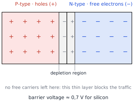
At the moment the two materials meet, the free electrons in the N side notice the holes right next to them and drift across. Each electron that crosses falls into a hole and both of them disappear as free carriers.
This does not go on forever. The N side has lost electrons, so it is left slightly positive near the border. The P side has gained them, so it is left slightly negative. That charge difference pushes back against any further electrons that try to cross.
The result is a thin layer around the border with no free carriers left in it: the depletion region. Across that layer sits a small built-in voltage that opposes the traffic, the barrier voltage:
- silicon: about 0,7 V
- germanium: about 0,3 V
Remember that 0,7 V. It comes back in every single calculation in this lesson.
Zero bias: nothing connected

Connect nothing, or connect a circuit with no source in it, and the junction just sits there. The depletion region keeps its own width, the barrier holds, and no current flows. This is the resting state of every diode in your drawer.
Reverse bias: pushing the wrong way
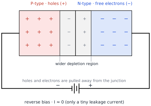
Now connect the minus of a supply to the P side and the plus to the N side.
The negative terminal attracts the holes in the P side and pulls them away from the border. The positive terminal does the same with the electrons in the N side. Both types of carrier retreat, so the depletion region gets wider and the barrier gets stronger.
Result: no current. Well, almost no current. A few electrons always get across because of heat, which gives a leakage current in the order of nanoamps to microamps. For our purposes it is zero.
But there is a limit. Turn the voltage up far enough and the electric field across that thin layer becomes so strong that it rips electrons out of their bonds. Current then shoots through and, in an ordinary diode, that is the end of the component. This is the breakdown voltage, and every diode datasheet lists it. Later in this lesson you will meet the zener diode, which is built to live in exactly that region.
Forward bias: pushing the right way

Turn the supply around: plus to the P side, minus to the N side.
Now the positive terminal pushes the holes towards the border and the negative terminal pushes the electrons towards it from the other side. The depletion region gets squeezed, and once the applied voltage exceeds the barrier voltage of about 0,7 V, it collapses. Electrons pour across, meet holes, and current flows freely.
Below 0,7 V: almost nothing happens. Above 0,7 V: the current rises extremely fast, and from that point on it is your resistor that has to limit it, not the diode.
The three states side by side
| Connection | Depletion region | Current | |
|---|---|---|---|
| Zero bias | nothing | normal width | none |
| Reverse bias | + to N, − to P | wider | none (only leakage) |
| Forward bias | + to P, − to N | collapses above 0,7 V | flows freely |
The Diode
Package that PN junction in a piece of glass or plastic with a wire at each end, and you have a diode.
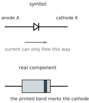
The two connections have names:
- The anode (A) is the P side. This is where the current goes in.
- The cathode (K) is the N side. This is where the current comes out.
The symbol is a memory aid all by itself: the triangle is an arrow that points in the direction the current can flow, and the bar is the wall that stops it going the other way. On the real component that bar is printed as a ring around the body, and that ring always marks the cathode.
Get the direction right the first time
A diode fitted the wrong way round does not blow up in a spectacular way. It simply does nothing, and your circuit stays dead while you look for a fault somewhere else. Before you push a diode into the breadboard, check the ring.
The characteristic curve
Everything a diode does is in one graph: the current through it as a function of the voltage across it.
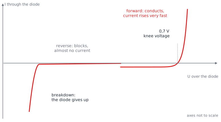
Read it from left to right:
- Far left, reverse: a big negative voltage, and still no current. Until the breakdown voltage, where the curve drops off a cliff.
- Around zero: nothing happens in either direction.
- Forward, below 0,7 V: still almost nothing. The barrier has not been beaten yet.
- Forward, at 0,7 V: the knee. The curve turns upward.
- Forward, above 0,7 V: the current explodes. A few hundredths of a volt more can double the current.
That last point is the practical lesson. A diode does not limit its own current. Once it conducts, it holds roughly 0,7 V across itself and lets through whatever the rest of the circuit allows. If nothing else in the circuit limits the current, the diode burns.
What matters on the datasheet
| Symbol | Name | What it means |
|---|---|---|
| forward voltage | the voltage the diode keeps for itself while conducting (≈ 0,7 V for silicon) | |
| forward current | the maximum current it can carry continuously | |
| or PIV | peak inverse voltage | the highest reverse voltage it can block without breaking down |
Two diodes you will meet all the time:
- 1N4148: a small signal diode. 100 V reverse, 200 mA forward, and very fast. Use it for logic, protection and small signals.
- 1N4007: a rectifier diode. 1000 V reverse, 1 A forward, slower. Use it for power supplies and for coils.
A Schottky diode is worth knowing about as well: it is built differently and only drops about 0,2 to 0,3 V, which saves energy in low-voltage circuits.
Example 1: Current through a diode circuit
A 5 V supply, a 220 Ω resistor and a silicon diode in series. How much current flows?
The diode keeps 0,7 V for itself, so the resistor gets the rest:
Note the method: first subtract the diode voltage, then apply Ohm's law to the resistor. You will use it in every diode calculation from here on.
Example 2: The same circuit, diode reversed
Same components, but the diode is turned around. Now what?
The diode blocks, so the current is zero (a few nanoamps of leakage, which we ignore). And because no current flows, there is no voltage across the resistor: V. The full 5 V therefore stands across the diode.
Try it yourself!
Question 1: A 9 V battery, a silicon diode and a 1 kΩ resistor in series, all in the conducting direction. What is the current?
Solution
Question 2: Two silicon diodes in series with a 470 Ω resistor on a 5 V supply, both diodes conducting. What is the current?
Solution
Each diode takes its own 0,7 V:
Question 3: You want 10 mA through a silicon diode on a 12 V supply. Which resistor do you need?
Solution
The nearest standard value is 1,2 kΩ, which gives 9,4 mA. Close enough.
The LED
An LED (light emitting diode) is a diode too, so everything above still applies: it conducts one way, blocks the other, and it has a knee voltage. The difference is what happens at the junction while it conducts.
Where the light comes from
In an ordinary silicon diode, an electron that falls into a hole releases its energy as heat. In an LED the semiconductor is not silicon but a compound such as gallium arsenide phosphide, chosen so that the energy comes out as light instead.
The size of the energy gap decides the colour of that light. A bigger gap means more energy per photon, which means bluer light, and it also means a higher forward voltage. Colour and forward voltage are two sides of the same coin:
| Colour | Typical | Typical current |
|---|---|---|
| Infrared | 1,2 V | 20 mA |
| Red | 1,8 – 2,2 V | 10 – 20 mA |
| Yellow / green | 2,0 – 2,4 V | 10 – 20 mA |
| Blue / white | 3,0 – 3,4 V | 10 – 20 mA |
So an LED does not drop 0,7 V. Using 0,7 V for an LED is one of the most common mistakes in first calculations.
Why an LED always needs a series resistor
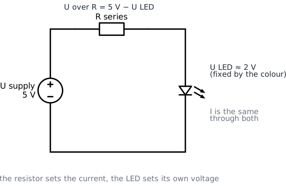
Look at the curve again. Above the knee, the current rises almost vertically. An LED connected straight across 5 V would try to draw an enormous current, heat up in milliseconds, and destroy its own junction. Sometimes it lights up beautifully for a second first.
The fix is the same as in lesson 1: put a resistor in series to set the current. The LED then decides its own voltage, and the resistor swallows the rest.
The formula follows directly from the series rule:
Example 1: A red LED on 5 V
You have a red LED ( V) and you want it to run at 15 mA.
200 Ω is not a standard value. Take the next value up, 220 Ω, because a bit less current is always safe:
That is exactly why 220 Ω is in your kit, and why you will use it in almost every LED circuit of this course.
Example 2: The same LED on 3,3 V
The Raspberry Pi Pico works at 3,3 V. Same LED, same 15 mA:
Take 100 Ω, which gives 13 mA. Notice how much smaller the resistor became: on a lower supply voltage there is less voltage left over for the resistor.
Example 3: A blue LED on 3,3 V
A blue LED needs 3,2 V. On a 3,3 V supply:
This circuit is a bad idea. There is only 0,1 V of headroom left, and the forward voltage of an LED varies from component to component and drifts with temperature. A tenth of a volt more or less doubles or kills your current. Blue and white LEDs belong on a 5 V supply, not on 3,3 V.
Check the power as well
The current also has to be safe for the pin that drives it, not only for the LED:
- Raspberry Pi Pico: keep a GPIO pin at 12 mA or less
- Arduino Uno R4: 20 mA is the working limit for a pin
An LED at 20 mA on a microcontroller pin is right at the edge. Design for 10 to 15 mA and everything stays comfortable. Modern LEDs are bright enough at 5 mA anyway.
Try it yourself!
Question 1: A green LED ( V) at 10 mA on a 5 V supply. Which resistor?
Solution
The nearest standard value up is 330 Ω (giving 8,8 mA). A 220 Ω resistor would give 13,2 mA, which is also fine but brighter and warmer.
Question 2: You have put a red LED ( V) in series with a 1 kΩ resistor on 5 V. How much current flows, and what does that mean for the brightness?
Solution
That is far below the usual 10 to 20 mA, so the LED will light up but dimly. Useful when you want a discreet indicator, or when you are short on current.
Question 3: How much power does the 220 Ω resistor from example 1 dissipate, and is a 0,25 W resistor good enough?
Solution
That is about one sixth of the rating, so yes, a standard 0,25 W resistor is fine.
Two Components You Need Next: the Capacitor and the Coil
To build a real power supply and to protect a relay, two more components are needed. You do not have to master them here; you need to know what they do.
The capacitor: a tiny rechargeable buffer
A capacitor is two metal plates with an insulator in between. Charge can pile up on the plates, so a capacitor stores energy in an electric field. The amount it can store is its capacitance, measured in farad (F). One farad is enormous, so real values are:
- µF (microfarad, 10⁻⁶): smoothing in power supplies, 1 µF to 10 000 µF
- nF (nanofarad, 10⁻⁹): filters and signals
- pF (picofarad, 10⁻¹²): high frequency
Because the plates are separated by an insulator, no DC current flows through a capacitor. Current only flows while the capacitor is charging or discharging. That gives it two behaviours worth remembering:
- For a steady DC voltage the capacitor eventually behaves like an open circuit: it is charged and everything stops.
- For a changing voltage current keeps flowing in and out, so the capacitor lets the changes through.
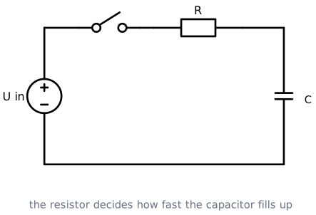
Charging is not instant. The resistor in the path limits the current, so the voltage across the capacitor creeps up along a curve:

The speed is set by the time constant:
with R in ohms, C in farads and τ in seconds. After one τ the capacitor is at 63 % of the supply voltage; after five τ it is at 99 %, which we call full. Discharging follows the same curve downwards.
Electrolytic capacitors have a polarity
The big cylindrical capacitors used for smoothing are electrolytic, and they have a + and a − leg. The − leg is marked with a stripe, and the − leg is usually the shorter one. Fit one the wrong way round and it will heat up, leak, and can burst. Also check the voltage rating: a 16 V capacitor on a 17 V peak is a bad plan.
Example: how fast does it charge?
A 10 kΩ resistor charges a 100 µF capacitor from a 5 V supply. How long until the capacitor is practically full?
After 1 s it sits at 63 % of 5 V = 3,15 V. After s it is at 99 %, so about 5 seconds.
The coil: a component that hates change
A coil (or inductor) is a wire wound into a spiral, often around an iron core. Where a capacitor stores energy in an electric field, a coil stores energy in a magnetic field. Its value is the inductance, measured in henry (H), usually mH or µH in practice.
The property that matters here is this: a coil resists any change in its current.
- Switch a coil on and the current does not jump to its final value, it ramps up while the magnetic field builds.
- Switch a coil off and the magnetic field collapses. All the stored energy has to go somewhere, and the coil generates whatever voltage it takes to keep its current flowing. That voltage is the wrong way round and can reach hundreds of volts.
That backwards voltage spike is called back-EMF, and it is the reason the flywheel diode further down this lesson exists. Anything with a coil in it, a relay, a motor, a solenoid valve, produces it.
Rectifiers: Turning AC into DC
Now everything comes together. A rectifier is a circuit that takes AC in and gives DC out, and it is built from nothing but diodes.
Never build these circuits on the mains
The circuits below are drawn with a transformer or a function generator, at voltages of a few volts. Mains voltage is lethal and is never part of a lab exercise in this course. In the lab you use the function generator, at a low voltage, and nothing else.
Half wave rectifier
The simplest rectifier is a single diode in series with the load.
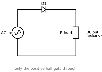
During the positive half of the input the diode is forward biased, so it conducts and the load gets the voltage (minus the 0,7 V the diode keeps). During the negative half the diode is reverse biased, blocks, and the load gets nothing at all.
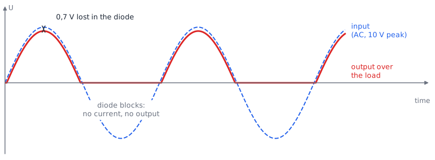
The output is DC in the sense that it never goes negative. But it is a very poor DC: half of the time there is nothing at all, and the average value is only
One diode, one component, half the energy thrown away. Good enough for a battery charger or a cheap LED lamp, not good enough for electronics.
Full wave rectifier with a centre tap
If we could use the negative half as well, we would double the output. That is what a full wave rectifier does. The classic version uses a transformer with an extra connection halfway along the secondary winding, the centre tap.
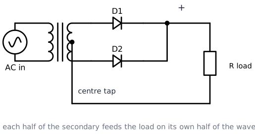
The centre tap is the reference point (0 V). Relative to it, the top half of the winding and the bottom half always have opposite polarity. So on every half of the wave, one of the two halves is positive, its diode conducts, and the load is fed. The other diode blocks and waits its turn.
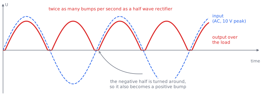
Twice as many bumps, twice the average:
The price is a special transformer, and the fact that each diode only ever uses half of the winding.
Bridge rectifier
The bridge rectifier achieves the same result with four diodes and an ordinary transformer, which is why it is what you find in practically every device today.
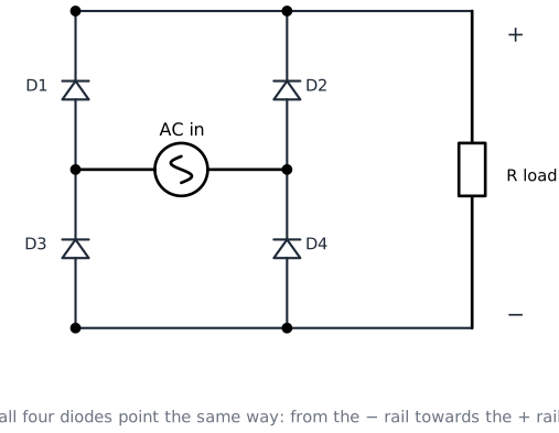
Look at the drawing carefully: all four diodes point the same way, from the − rail up towards the + rail. That is the whole trick. Whatever the input does, the only path the current can take through the load is downwards.
During the positive half, D1 and D4 conduct while D2 and D3 block:

During the negative half, D2 and D3 take over:

The current through the AC source reverses every half period, but the current through the load runs in the same direction both times. The two diodes in the path each keep 0,7 V, so a bridge costs 1,4 V:
The three side by side
| Diodes | Transformer | Output bumps per period | Average | Diode drop | |
|---|---|---|---|---|---|
| Half wave | 1 | ordinary | 1 | 0,318 × U peak | 0,7 V |
| Full wave, centre tap | 2 | with centre tap | 2 | 0,637 × U peak | 0,7 V |
| Bridge | 4 | ordinary | 2 | 0,637 × U peak | 1,4 V |
Smoothing: the capacitor fills the gaps
A rectified signal is DC, but it is still a series of bumps. No microcontroller will run on that. Put a capacitor in parallel with the load and the picture changes completely.
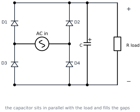
The capacitor charges up to the peak of each bump. When the bump falls away, the diodes stop conducting and the capacitor takes over, feeding the load out of its own stored charge until the next bump arrives and tops it up.

What is left over is a small sawtooth on top of the DC, called the ripple. How big it is depends on three things:
- a bigger capacitor stores more charge, so less ripple
- a bigger load current empties it faster, so more ripple
- more bumps per second gives the capacitor less time to sag, so less ripple (another reason to prefer a bridge over a half wave)
For a full wave rectifier on a 50 Hz supply, the gap between bumps is s.
Example: designing a small DC supply
A 12 V AC transformer feeds a bridge rectifier with a 1000 µF smoothing capacitor. The load draws 100 mA. What comes out?
Step 1: peak of the input
Step 2: subtract the two diodes
Step 3: the ripple
Result: the output sits between 14,6 V and 15,6 V. Notice that a "12 V" transformer produced roughly 15 V DC, and that the capacitor has to survive 17 V, so a 25 V capacitor is the sensible choice.
Try it yourself!
Question 1: A 9 V AC transformer feeds a bridge rectifier. What is the peak DC voltage over the smoothing capacitor?
Solution
Question 2: The same supply feeds a load of 50 mA through a 470 µF capacitor at 50 Hz. How large is the ripple?
Solution
The output therefore wobbles between about 10,2 V and 11,3 V.
Question 3: You want to halve that ripple. Name two ways to do it.
Solution
- Double the capacitor to 1000 µF, so it holds twice the charge.
- Halve the load current, if the design allows it.
(Going from a half wave to a full wave rectifier would also halve it, but this circuit is already a bridge.)
The Flywheel Diode
A relay, a motor and a solenoid all contain a coil, and a coil fights back when you switch it off. The flywheel diode (also called a freewheeling or snubber diode) is the standard answer.

The diode is placed in parallel with the coil, and against the supply direction: the cathode goes to the + side. That means that during normal operation the diode is reverse biased and does nothing at all.
The moment the switch opens, everything changes. The collapsing magnetic field drives the coil to produce a voltage that is the other way round, and suddenly the diode is forward biased. The coil's current now runs in a harmless little circle through the diode and dies out as heat, instead of arcing across your switch or punching through the transistor or microcontroller pin that was driving it.
No flywheel diode, no transistor
Without this diode the voltage spike from a small 5 V relay can easily reach 100 V or more. That kills switching transistors and microcontroller outputs, and it does it silently: the circuit often works for hours before it fails. The relay board in your kit already has these diodes built in, every proper relay module does.
For this job you want a diode that can carry the coil current and switch reasonably fast. A 1N4007 works for relays and small motors.
The Zener Diode
Ordinary diodes die in reverse breakdown. A zener diode is doped so that its breakdown is sharp, precise and completely reversible, and it is designed to be used there.
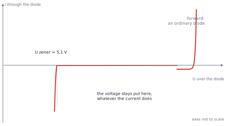
Forward, it behaves like any silicon diode: 0,7 V and it conducts. Reverse, nothing happens until the zener voltage , and from there the curve goes almost straight down. That vertical part is the useful bit: no matter how the current changes, the voltage across the diode stays at .
Zeners are sold in standard values: 2,4 V, 3,3 V, 4,7 V, 5,1 V, 6,2 V, 9,1 V, 12 V and so on.
A zener as a voltage regulator
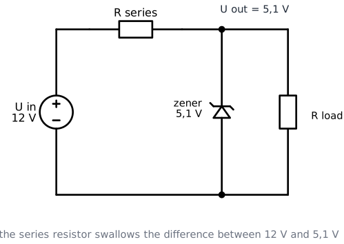
Note the direction: the zener is fitted in reverse, with its cathode (the ring) towards the plus. Together with a series resistor it makes the simplest voltage regulator there is.
The series resistor drops the difference between the input voltage and the zener voltage. The zener then takes whatever current is left over after the load has taken its share, and by doing so it keeps the output voltage nailed to :
- if the load takes more current, the zener takes less
- if the load takes less, the zener takes more
- either way the total current through the resistor barely changes, and so does the output voltage
The resistor is calculated for the worst case, which is the maximum load current:
A few milliamps of (5 mA is a good rule of thumb) keeps the zener inside its vertical region.
Example: a 5,1 V supply from 12 V
You have 12 V and a circuit that needs 5,1 V at up to 20 mA.
Step 1: the series resistor
Take the nearest standard value below, 270 Ω, so there is certainly enough current.
Step 2: check the power in the resistor
A 0,25 W resistor survives this, but only just. A 0,5 W type would be more comfortable.
Step 3: check the power in the zener, with no load connected
This is the worst case for the diode, because then it has to swallow the whole current itself:
A common 0,5 W zener handles that easily.
When not to use a zener
This circuit wastes energy all the time: the resistor and the diode keep drawing current even when the load needs nothing. It is fine for a reference voltage or a few milliamps. For anything bigger, use a proper voltage regulator IC such as a 7805 (5 V) or an LM1117 (3,3 V). They cost the same, waste less, and hold their voltage far better. The zener is still the component that teaches you why they work.
Clipping
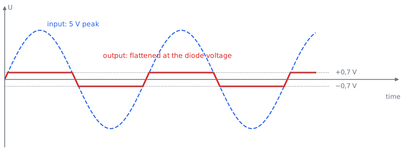
The last trick uses the fact that a conducting diode holds a fixed voltage. If you put diodes across a signal, the signal simply cannot get past that voltage. This is called clipping or limiting.
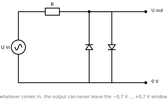
Two diodes are placed in parallel with the output, pointing in opposite directions. As long as the signal stays between −0,7 V and +0,7 V, both diodes are below their knee and do nothing at all. As soon as it tries to go higher, the upper diode conducts and holds the output; below −0,7 V the other one does the same.
The series resistor is essential: it takes the difference between the input and the clipped output. Without it, the diodes would short out the source.
Where you meet this in practice:
- Input protection. Two diodes from an input pin to 0 V and to the supply keep any voltage on that pin inside the safe range. Almost every microcontroller has these built in.
- Distortion effects. The fuzz pedal of an electric guitar is exactly this circuit; clipping a sine wave makes it sound like a square wave.
- Signal shaping, when you need a rough square wave from something that is not one.
Key Takeaways
DC keeps its direction, AC does not. AC is described by its period, frequency, peak, peak-to-peak and RMS value.
RMS is the DC-equivalent value. . With RMS values, Ohm's law and the power formulas work unchanged.
Semiconductors have four valence electrons. Doping adds free electrons (N-type) or holes (P-type).
A PN junction builds its own barrier, about 0,7 V for silicon, in a thin depletion region.
Forward bias collapses that barrier and current flows; reverse bias widens it and current stops. That is the whole diode.
A diode does not limit its own current. Above the knee it keeps roughly 0,7 V and lets everything through, so something else must limit the current.
An LED needs a series resistor: , with depending on the colour, not on 0,7 V.
A capacitor stores charge in an electric field; a coil stores energy in a magnetic field and fights every change in current.
Rectifiers turn AC into DC: one diode for half wave, two plus a centre tap for full wave, four for a bridge. A bridge costs 1,4 V and is what everything uses.
A smoothing capacitor turns bumps into a nearly flat voltage, with a ripple of .
A flywheel diode across every coil catches the back-EMF and protects whatever is switching.
A zener works in reverse on purpose and holds a fixed voltage, which makes a simple regulator or a reference.
Glossary: Key Terms and Abbreviations
These are the new terms from this lesson. The terms from lesson 1 still apply and are not repeated here.
AC (Alternating Current)
A voltage or current that repeatedly changes direction. The mains and a function generator supply AC.
Anode
The P side of a diode, the terminal where the current enters when the diode conducts.
Back-EMF
The reverse voltage a coil produces when its current is interrupted and its magnetic field collapses. It can reach hundreds of volts and destroys unprotected electronics.
Barrier voltage
The built-in voltage across the depletion region of a PN junction: about 0,7 V for silicon and 0,3 V for germanium. Also called the knee voltage or threshold voltage.
Breakdown voltage
The reverse voltage at which a diode stops blocking and suddenly conducts. Fatal for an ordinary diode, the working point for a zener.
Bridge rectifier
A rectifier made of four diodes that uses both halves of the AC wave without needing a centre-tapped transformer. Costs two diode drops (1,4 V).
Capacitance
The ability of a capacitor to store charge, measured in farad (F). Practical values are µF, nF and pF.
Capacitor
Two plates separated by an insulator, storing energy in an electric field. Blocks DC, passes changes.
Cathode
The N side of a diode, the terminal where the current leaves. Marked with a ring on the body of a real diode, and the short leg on an LED.
Clipping
Cutting the tops off a signal by letting diodes conduct above a fixed voltage. Used for input protection and for distortion effects.
DC (Direct Current)
A voltage or current that keeps the same direction. Batteries, USB and bench supplies deliver DC.
Depletion region
The thin layer around a PN junction that has no free charge carriers left. It gets wider in reverse bias and collapses in forward bias.
Doping
Deliberately adding a trace of another element to pure silicon to create N-type or P-type material.
Electrolytic capacitor
A high-capacitance capacitor with a + and a − terminal. Fitting it the wrong way round destroys it.
Farad (F)
The unit of capacitance. One farad is very large; real components are in µF, nF or pF.
Flywheel diode
A diode in parallel with a coil, reverse biased in normal operation, that catches the back-EMF when the coil is switched off. Also called a freewheeling or snubber diode.
Forward bias
Connecting a diode with + on the anode and − on the cathode, so it conducts.
Forward voltage (UF)
The voltage a diode keeps for itself while conducting: about 0,7 V for silicon, 0,2 to 0,3 V for a Schottky, and 1,8 to 3,4 V for an LED depending on its colour.
Frequency (f)
How many complete periods fit in one second, in hertz (Hz). .
Full wave rectifier
A rectifier that uses both halves of the AC wave. Either two diodes with a centre-tapped transformer, or four diodes in a bridge.
Half wave rectifier
A rectifier with a single diode that passes only the positive half of the wave and throws the rest away.
Henry (H)
The unit of inductance. Practical coils are in mH or µH.
Hertz (Hz)
The unit of frequency: one period per second.
Hole
An empty place in the bond structure of P-type silicon where an electron is missing. It moves through the material and behaves like a positive charge carrier.
Inductor (coil)
A wound wire that stores energy in a magnetic field and resists any change in its current.
Leakage current
The very small current (nA to µA) that still flows through a reverse biased diode.
N-type
Silicon doped with an element that has five valence electrons, giving a surplus of free electrons.
P-type
Silicon doped with an element that has three valence electrons, giving a surplus of holes.
Peak value
The highest voltage a signal reaches, measured from the zero line.
Peak-to-peak value
The distance from the lowest to the highest point of a signal. For a sine wave, twice the peak value.
Period (T)
The time one complete cycle of a repeating signal takes, in seconds.
PIV (Peak Inverse Voltage)
The maximum reverse voltage a diode can block. Also written as UR or VRRM on datasheets.
PN junction
The border between P-type and N-type material. The basis of every diode, LED and transistor.
Rectifier
A circuit that converts AC into DC using diodes.
Reverse bias
Connecting a diode with + on the cathode and − on the anode, so it blocks.
Ripple
The small remaining variation on top of a smoothed DC voltage. .
RMS (Root Mean Square)
The DC voltage that would produce the same heating as the AC signal. For a sine wave, .
Schottky diode
A diode built with a metal-semiconductor junction. Lower forward voltage (0,2 to 0,3 V) and very fast.
Semiconductor
A material with four valence electrons, such as silicon, that conducts better than an insulator and worse than a conductor, and whose behaviour can be changed by doping.
Sine wave
The smooth, repeating shape of the voltage delivered by the mains and by a function generator in sine mode.
Smoothing capacitor
A capacitor across the output of a rectifier that charges to the peaks and supplies the load in between, turning bumps into a nearly flat voltage.
Time constant (τ)
, the time in which a capacitor charges to 63 % of the supply voltage. After 5 τ it is practically full.
Transformer
Two coils around a common core that convert one AC voltage into another. Does not work on DC.
Valence electrons
The electrons in the outermost shell of an atom. Their number decides whether a material is a conductor, a semiconductor or an insulator.
Zener diode
A diode designed to break down at a precise reverse voltage and to survive it, used to hold a fixed voltage.
Zener voltage (UZ)
The reverse voltage at which a zener diode starts to conduct and which it then holds.
Extra Resources
- All About Circuits: Diodes and Rectifiers: the full textbook chapter, with more depth on every circuit in this lesson
- Electronics Tutorials: Diode Rectifiers: half wave, full wave and bridge with worked examples
- LED series resistor calculator: check your own calculations, but do the maths first
- Falstad circuit simulator: draw a bridge rectifier in the browser and watch the current change direction in slow motion