
Lab 5: Numeral Systems
1. Assignment description
In this lab you will build a small application on the Arduino UNO R4 that visualises numbers in different numeral systems. You will connect 8 LEDs to display binary values, read input from the serial monitor, and use a potentiometer as an analogue input source. At the end of the lab, you will also connect an OLED screen to display the values.
The lab is built up step by step. Each step extends the program from the previous one, so do not skip steps.
What we expect:
- A working Arduino sketch that meets the requirements of each step
- Clean and readable code with clear function names
- Photos or screenshots where indicated
- A short reflection of approximately half a page in Chapter 3
Step 2.8 is optional
Step 2.8 is not graded. It is intended for students who finish early.
2. Lab
By the end of this lab, you will have a program that reads a number from the serial monitor, displays it on 8 LEDs in binary form, reads a potentiometer value in real time and shows all values on an OLED screen.
2.1 Connecting 8 LEDs
What do we need?
- 1x Arduino UNO R4
- 4x LED (green)
- 4x LED (red)
- 8x 220 ohm resistor
- Jumper wires
- Breadboard
Connect the LEDs to digital pins 2 through 9. Use the schematic below. Make sure every LED has a 220 ohm resistor in series.
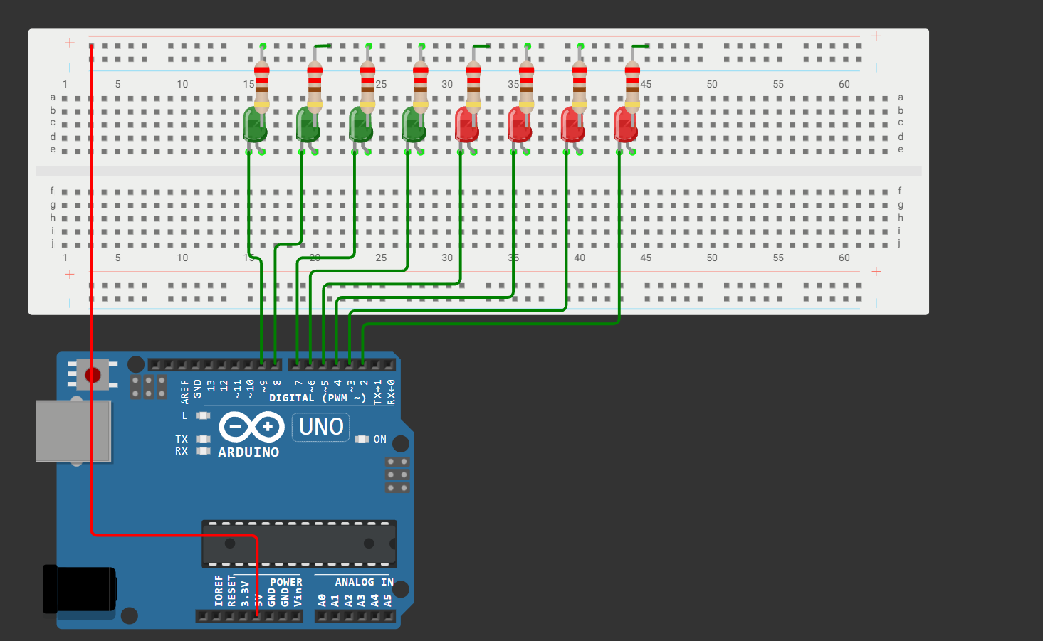
Write a sketch that turns on all LEDs. This confirms that all your connections are correct.
Take a picture of your setup.
2.2 Reading a decimal number
The user types a decimal number (0 to 255) in the serial monitor. The Arduino reads this number and displays it in binary on the 8 LEDs. A number greater than 255 is not allowed.
To convert a decimal number to binary we divide repeatedly by 2 and keep track of the remainders. The remainders read from bottom to top give us the binary number.
88 (base 10) =
01011000(base 2)
Group your results in a struct. This makes it easy to extend the program in the next steps.
struct NumberResult {
  String decimal;
  String binary;
};
Write the following functions:
decimalToBinary(int value)returns aStringof 8 bitsupdateLeds(String binary)turns the correct LEDs on or offisValidDecimal(String input)checks whether the input contains only digits and is not greater than 255translate(String input, String inputType)fills the struct and returns it
In loop(): ask the user for a decimal number, validate it, call translate and display the result on the LEDs.
Type 88 in the serial monitor. Do the LEDs show 01011000? Take a picture of the result.
2.3 Reading a binary number
Extend the program so the user can also type a binary number. The Arduino converts it to decimal and displays it on the LEDs.
Write the following functions:
binaryToDecimal(String input)returns an integerisValidBinary(String input)checks whether the input contains only 0s and 1s and is not longer than 8 characters
In loop(): ask the user which format they want to use (decimal or binary), validate it, call translate and display the result on the LEDs.
Type binary and then 01011000 in the serial monitor. Do the LEDs show 01011000? Take a picture of the result.
2.4 Connecting a potentiometer
What do we need?
- 1x potentiometer
- Jumper wires
Connect the potentiometer to pin A0. Use the schematic below.
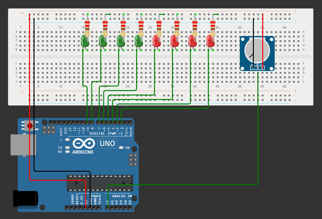
Write a small test sketch that reads the potentiometer value every 500 ms and prints it to the serial monitor.
Do you see a value between 0 and 255 when you turn the potentiometer? Take a screenshot of the serial monitor.
2.5 Letting the user choose the input format
Combine everything from the previous steps. The user can now choose between three input options: decimal, binary or potentiometer.
In loop():
- Ask the user which format they want to use and validate the input
- For decimal and binary: ask for a number, validate it and display it on the LEDs
- For potentiometer: read the value once, pass it through
translateand display it on the LEDs
Turn the potentiometer fully to the left. Select potentiometer and take a picture of the result.
Turn the potentiometer fully to the right. Select potentiometer and take a picture of the result.
Can you explain why you see these results?
2.6 Live mode
Replace the potentiometer option with a live mode. In live mode the Arduino reads the potentiometer every 500 ms and updates the LEDs automatically. The user can stop live mode by typing anything in the serial monitor.
Changes to make:
- Replace
potentiometerwithliveas an input option - In live mode: use a
while(true)loop that reads the potentiometer every 500 ms and updates the LEDs - At the start of every loop: check if the user has typed something with
Serial.available(). If so, exit the loop.
Does the live mode update every 500 ms? Does it stop when you type something in the serial monitor?
Take a series of pictures showing the LEDs changing as you turn the potentiometer.
2.7 Connecting the OLED screen
What do we need?
- 1x Adafruit OLED 1.3" (SSD1306)
- Jumper wires
Connect the OLED screen via I2C.
Install the following libraries via the Arduino Library Manager:
Adafruit SSD1306Adafruit GFX
Write a function updateScreen(String dec, String bin, int potValue) that displays the values on the OLED screen. Call this function every time the LEDs are updated. The screen should show:
POT: 88
DEC: 88
BIN: 01011000
Take a picture of the OLED screen after entering 88.
Paste your full code.
2.8 Extra: Hexadecimal input and output
This step is optional and is not graded.
Add hexadecimal as a fourth input option. The user can now type a hex value like 0x58 and see it displayed on the LEDs.
Changes to make:
- Add
hexas an input option - Write a function
hexToDecimal(String input)that converts a hex string to decimal - Write a function
decimalToHex(int value)that converts a decimal value to a hex string - Add the hex value to the OLED screen display
Take a picture of the result after entering 0x3F.
Paste your full code.
3. Reflection
Write a short reflection of approximately half a page (font: Arial 9.5). Answer the following questions in your own words:
What did you learn?
Which concepts from the theory did you recognise in the lab? Give a concrete example.
What was difficult?
Which step gave you the most trouble? How did you solve it?
What would you do differently?
If you had to redo this lab, what would you approach differently?
Connection to IoT
Can you think of a real IoT situation where numeral systems play a role? Give one example and explain why.