
Binary Logic
How do computers make "decisions"?
In the previous lesson you learned that computers work exclusively with 0s and 1s. Knowing how to represent numbers in binary is only the first step. The real power of digital systems lies in the ability to combine those 0s and 1s to make decisions. That is what binary logic is about.
Analog vs Digital
Before diving into logic gates, it helps to understand the fundamental difference between analog and digital signals.
An analog signal is continuous. It can take on any value within a range, with infinitely many possible intermediate values. A temperature reading from a thermometer, the voltage output of a microphone, or the position of a dimmer switch are all analog. The real world is mostly analog.

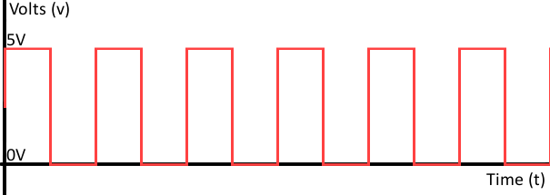
A digital signal is discrete. It can only take on a limited number of distinct values. In binary digital systems, there are exactly two: 0 and 1. This maps perfectly onto the two physical states of a transistor: either conducting (current flows) or not conducting (no current). This is why digital systems are so practical to build in hardware.
| Property | Analog | Digital |
|---|---|---|
| Signal | Continuous | Discrete |
| Possible values | Infinite | 2 (in binary) |
| Real-world example | Temperature | Light switch |
The transition from the physical world to digital values requires a choice of threshold. A voltage above a certain level is interpreted as 1, below it as 0. Everything in between is ambiguous and avoided by design.
From electricity to 0 and 1
You already know from the previous chapter that a wire either has voltage or it does not. Binary logic builds directly on this: those two electrical states become the inputs and outputs of logical operations.
By combining inputs, we can determine an output that depends on a fixed rule. For example, we might want an output of 1 only when two specific inputs are both 1. Or we might want to invert a signal: turning a 0 into a 1 and vice versa. Each of these operations is carried out by a logic gate.
What is a logic gate?
A logic gate is a small electronic component that takes one or more binary inputs and produces one binary output based on a fixed rule. Inside a chip, a logic gate is built from a few transistors wired together in a specific pattern. To the outside world, all that matters is the rule it implements.
Consider a practical example: a security system with two sensors.
- Sensor A detects motion
- Sensor B detects that a door is open
- The alarm should only go off when both sensors are active at the same time
The rule "both must be active" is exactly what an AND gate does. Change the rule to "at least one must be active" and you have an OR gate. Change it to "invert the signal" and you have a NOT gate. Every gate has its own fixed rule.
What is a truth table?
A truth table is a systematic way of listing every possible combination of inputs and the corresponding output for a given gate.
For a gate with 2 inputs (A and B), there are always 4 possible combinations, since each input can independently be 0 or 1:
| A | B | Output |
|---|---|---|
| 0 | 0 | ? |
| 0 | 1 | ? |
| 1 | 0 | ? |
| 1 | 1 | ? |
The rule of the gate determines what fills in the Output column. For a gate with 1 input there are 2 combinations. For 3 inputs there are 8. The number of combinations is always 2^n where n is the number of inputs.
Truth tables are the standard notation in datasheets and technical documentation. Being able to read and write them is an essential skill.
Truth table over time
A truth table shows all combinations in a static table. You can also draw the same information as a signal diagram over time: a waveform. The rule is:
- Read the values of A, B, ... at a given moment in time
- Look up the corresponding output in the truth table
- Draw the output signal accordingly

This kind of timing diagram appears regularly in datasheets. When you work with sensors, registers and communication protocols, you will often need to interpret exactly this type of diagram.
IEC symbols
Logic gates have standardised graphical symbols. In Europe, the IEC (International Electrotechnical Commission) symbols are used. In the United States you will often encounter ANSI symbols instead, which look quite different. You will see both in datasheets.

The IEC symbol convention:
- Inputs are always on the left, outputs on the right
- A triangle or circle on the output means the active output is 0 (inverted)
- The inner symbol indicates how many inputs must be active to make the output active
Logic gate chips are identified by codes like 74HC04:
74indicates the commercial IC seriesHCindicates the technology (in this case High-speed CMOS)04indicates the function (in this case an inverter or NOT gate)
The NOT gate
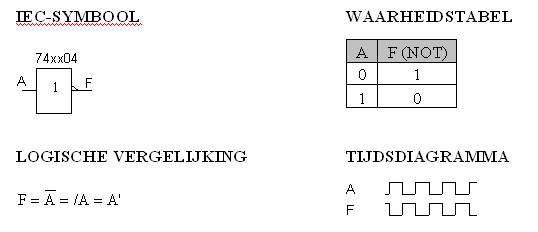
The NOT gate is the simplest gate. It has exactly one input and one output, and its rule is: invert the input. If the input is 0, the output is 1. If the input is 1, the output is 0. It is often called an inverter.
The NOT gate is used when you need the opposite of a signal. For example, if a sensor outputs 1 when active and you need to trigger something when the sensor is inactive, you pass the signal through a NOT gate first.
The AND gate
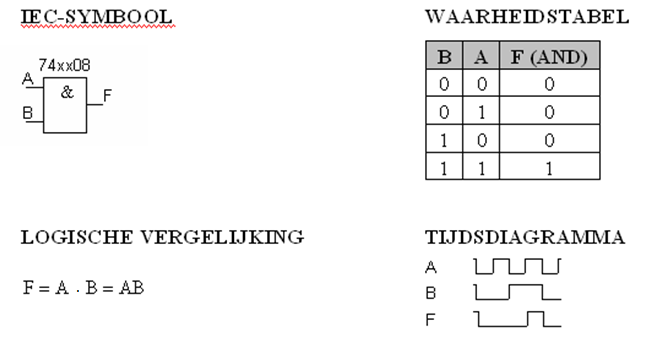
The AND gate has two or more inputs and one output. Its rule: the output is 1 only when all inputs are 1. If any input is 0, the output is 0.
Think of it as a series circuit: current only flows when both switches are closed. In IoT, the AND gate represents a condition where multiple requirements must all be met simultaneously: for example, a system that only activates when both a motion sensor AND a door sensor are triggered.
The OR gate
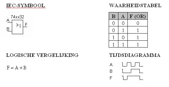
The OR gate has two or more inputs and one output. Its rule: the output is 1 when at least one input is 1. The output is only 0 when all inputs are 0.
Think of it as a parallel circuit: current flows when at least one switch is closed.
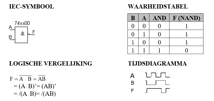
The NAND gate
The NAND gate is an AND gate followed by a NOT gate. Its output is the inverse of AND: the output is 0 only when all inputs are 1. For every other combination, the output is 1.
The NAND gate is particularly important because it is functionally complete. Any logic circuit, no matter how complex, can be built using only NAND gates. This makes it one of the most common gates in chip design.
The NOR gate
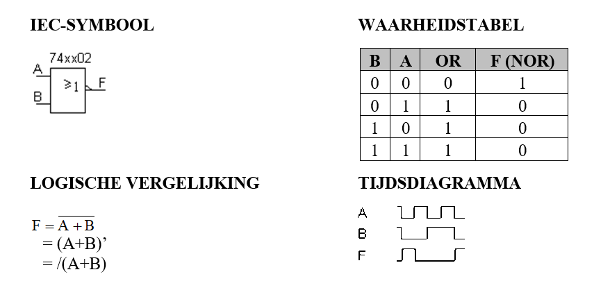
The NOR gate is an OR gate followed by a NOT gate. Its output is the inverse of OR: the output is 1 only when all inputs are 0. If any input is 1, the output is 0.
Like the NAND gate, the NOR gate is also functionally complete. You can build any circuit from NOR gates alone.
The XOR gate
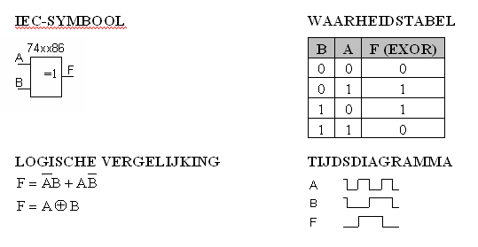
The XOR gate (Exclusive OR) is active only when exactly one input is 1. If both inputs are 0 or both are 1, the output is 0. It can be thought of as "one or the other, but not both."
XOR is commonly used in binary arithmetic (it performs addition without carry) and in error detection and encryption circuits.
The XNOR gate
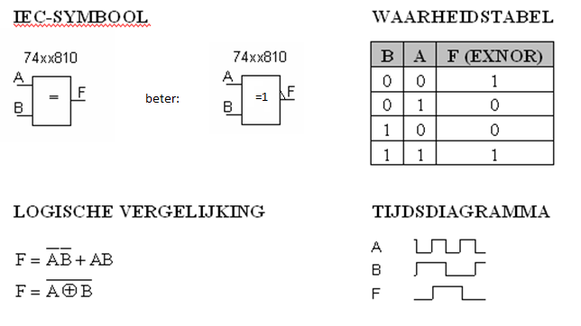
The XNOR gate (Exclusive NOR) is the inverse of XOR. Its output is 1 when both inputs are equal (both 0 or both 1), and 0 when they differ.
XNOR is used for equality comparison: a compact way of checking whether two bits have the same value.
Logic functions in words
Here is a concise summary of how each gate behaves:
| Gate | Output is 1 when... | Output is 0 when... |
|---|---|---|
| NOT | the input is 0 | the input is 1 |
| AND | all inputs are 1 | at least one input is 0 |
| OR | at least one input is 1 | all inputs are 0 |
| NAND | at least one input is 0 | all inputs are 1 |
| NOR | all inputs are 0 | at least one input is 1 |
| XOR | exactly one input is 1 | all inputs are equal |
| XNOR | all inputs are equal | exactly one input is 1 |
ANSI vs IEC symbols
Both symbol systems are in common use. You will encounter both in datasheets and textbooks.
| Gate | ANSI shape | IEC inner symbol |
|---|---|---|
| NOT | Triangle with bubble | 1 + circle on output |
| AND | D-shape | & |
| OR | Curved shield | ≥1 |
| NAND | D-shape + bubble | & + circle |
| NOR | Curved shield + bubble | ≥1 + circle |
| XOR | Curved shield + extra curve | =1 |
| XNOR | Curved shield + bubble | =1 + circle |
Integrated circuits and DIP packages
In practice, logic gates are not built one by one from transistors. Instead, they come packaged as integrated circuits (ICs): small chips that contain multiple gates in a single package.

A common physical form is the DIP (Dual Inline Package). A DIP chip has two rows of pins that plug into a breadboard. Each pin has a specific function defined in the chip's datasheet.
A few things to know about DIP chips:
- Pins are numbered starting from 1
- A notch at one end of the chip marks the orientation. Pin 1 is to the left of the notch when the notch faces away from you
- Sometimes a dot marks pin 1 directly
- The datasheet tells you which pin does what: inputs, outputs, VCC (power) and GND
For example, the 74HC08 chip contains four 2-input AND gates. Its datasheet shows exactly which pins connect to which gate inputs and outputs, and which pins supply power and ground.
In more complex systems, instead of discrete logic gate chips, engineers use microcontrollers or FPGAs that implement the same logic in software or programmable hardware. But understanding the gate level helps you reason about what the hardware is actually doing. This is essential when you read a datasheet or debug a digital circuit.