
Lab 4: Op-Amps
1. Assignment description
In this lab you build the two components that can make something bigger than it was. First the transistor, used as a switch, which is what a microcontroller does every time it drives a relay or a motor. Then the LM741, wired up as four different amplifiers, each one decided by nothing more than two resistors.
Nothing here is new instrument work. You know the supply, the multimeter, the function generator and the scope. What is new is that the supply now has to deliver a negative voltage as well.
What we expect:
- Every measurement table filled in, with units
- Every resistor value calculated before you build, not chosen afterwards
- Photos of your circuits and of the scope screen where indicated
- A short reflection of approximately half a page in Chapter 3
Planning
| When | Steps | What you do |
|---|---|---|
| Theory lesson (last 1,5 h) | 2.1 to 2.2 | The transistor as a switch, and finding where it switches |
| Lab session (3 h) | 2.3 to 2.7 | Dual supply, inverting amplifier, non-inverting amplifier, adder, subtractor |
| If you finish early | 2.8 to 2.9 | Comparator with an LED, and pushing the op-amp past its limits. Not graded |
What do we need?
From your own kit:
- 1x breadboard and jumper wires
- 3x red LED, 3x 220 Ω
- 2x 1 kΩ, 5x 10 kΩ
- 2x 10 kΩ potentiometer
From the lab room:
- Bench supply (both channels), multimeter, function generator, oscilloscope with a ×10 probe
- 1x NPN transistor (BC547, 2N2222 or similar)
- 1x LM741
Safety rules for this lab
- Never leave out the base resistor. Without it the base of the transistor is a diode straight across your source.
- Check your dual supply with the multimeter before you plug the LM741 in. Swapping +12 V and −12 V on the chip destroys it in seconds, and you will smell it.
- Turn the supply voltages down to 0 V before you rewire anything, exactly as in lab 1.
- An LED never goes in without its series resistor.
- If a component feels hot, turn the supply down first and ask afterwards.
2. Lab
2.1 The transistor as a switch
A microcontroller pin can deliver about 12 mA. Three LEDs need three times that. The transistor is the component that bridges the gap.
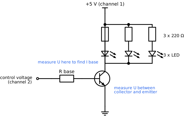
What do we need? 1x NPN transistor, 3x LED, 3x 220 Ω, 1x 1 kΩ, both supply channels.
Step 1: Calculate the base resistor
Work through it in the same order as in the theory.
- Each LED branch carries . Use the LED voltage you measured in lab 2, or 2,0 V.
- Three branches in parallel, so the collector current is three times that.
- Assume the worst case for the current gain, β = 100, and calculate the minimum base current.
- Multiply that by 5, so the transistor really saturates.
- Calculate the base resistor with , and pick the nearest value from your kit.
Step 2: Build it
- Both supply voltages to 0 V first.
- Build the circuit. The flat side of the transistor tells you which leg is which, so check its datasheet or the marking on the component before you push it in.
- Set channel 1 to 5,0 V for the LED branches, and channel 2 to 0 V: that channel is your control voltage.
- Current limit on both channels at 100 mA.
Step 3: Off and on
Set the control voltage to 0 V, then to 3,3 V, and fill in the table. You get the base current from the voltage across the base resistor, and the collector current from the voltage across one of the 220 Ω resistors.
| Measurement | Control at 0 V | Control at 3,3 V |
|---|---|---|
| LEDs on or off | ||
| U over the base resistor | ||
| I base (calculated) | ||
| U between base and emitter | ||
| U between collector and emitter | ||
| U over one 220 Ω resistor | ||
| I collector (calculated, three branches) |
Take a picture of the circuit with the LEDs on.
Divide your measured collector current by your measured base current. Is that number the β of your transistor? Explain your answer.
2.2 Where exactly does it switch?
The transistor does not switch at 0 V and it does not switch at 3,3 V. Find out where it does.
Turn the control voltage up in the steps below, and each time note what you see and measure.
| Control voltage | U base to emitter | U collector to emitter | LEDs (off, dim, bright) |
|---|---|---|---|
| 0 V | |||
| 0,4 V | |||
| 0,6 V | |||
| 0,7 V | |||
| 0,8 V | |||
| 1,0 V | |||
| 2,0 V | |||
| 3,3 V |
Between which two control voltages does the transistor go from off to fully on?
Pick a row where the LEDs are dim and the collector to emitter voltage is somewhere between 1 V and 4 V. That is the active region. Calculate β for that row.
Calculate the power in the transistor for that same row, and for the row at 3,3 V. Which of the two would get hot in a real circuit?
2.3 A dual supply and the LM741
Everything from here on needs a supply that can go below 0 V. You make one from the two channels you already have.
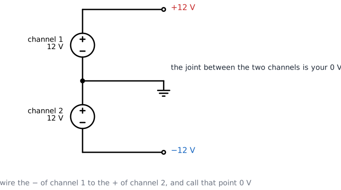
Step 1: Build the supply
- Both channels to 0 V, current limit 100 mA.
- Wire the − terminal of channel 1 to the + terminal of channel 2. That joint is your 0 V, and it goes to the − rail of your breadboard.
- The + of channel 1 becomes +12 V, the − of channel 2 becomes −12 V.
- Turn both channels up to 12,0 V.
Step 2: Check before you plug anything in
Measure with the multimeter, black probe on your 0 V joint.
| Measurement | Expected | Measured |
|---|---|---|
| 0 V to the + of channel 1 | +12 V | |
| 0 V to the − of channel 2 | −12 V | |
| − of channel 2 to + of channel 1 | 24 V |
Why does the third measurement show 24 V and not 12 V?
Step 3: Wire the chip
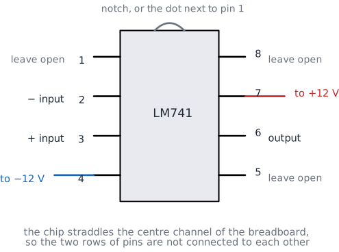
- Supplies back to 0 V.
- Push the LM741 across the centre channel of the breadboard, so that the two rows of pins land in different columns.
- Find pin 1 with the notch or the dot. Pin 1 is at the top left, and the numbers run down the left side and back up the right side.
- Wire pin 7 to +12 V and pin 4 to −12 V. Check twice.
- Turn the supplies back up and touch the chip briefly. It should stay cold.
If the chip gets warm with nothing else connected
Turn the supply down immediately. It means the two supply pins are swapped, or one of them is shorted to the other rail. Rewire before you continue.
2.4 Inverting amplifier
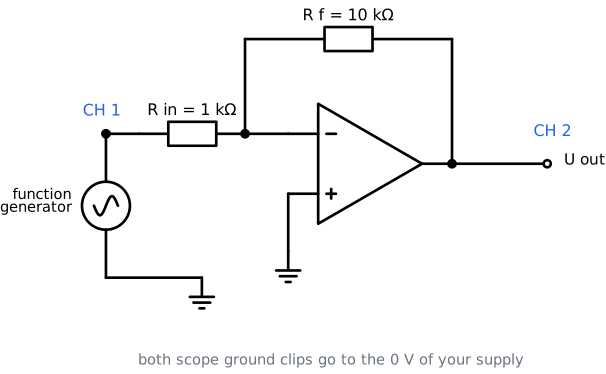
Build: R in = 1 kΩ from the generator to pin 2, R f = 10 kΩ from pin 6 back to pin 2, and pin 3 straight to 0 V.
Generator: sine, 1 kHz, amplitude set with the scope to 0,5 Vpp.
Scope: CH1 on the input, CH2 on the output, both ground clips on your 0 V.
Step 1: Measure the gain
| Quantity | Calculated | Measured |
|---|---|---|
| Gain, from R f / R in | ||
| U in (Vpp) | ||
| U out (Vpp) | ||
| Gain, from U out / U in |
Take a picture of the screen with both traces.
Look at the two traces together. What does the output do while the input is going up? Which word in the name of this circuit does that explain?
Step 2: Change the gain
Replace R in with a 10 kΩ resistor and measure again.
| R in | R f | Gain calculated | U out (Vpp) | Gain measured |
|---|---|---|---|---|
| 1 kΩ | 10 kΩ | |||
| 10 kΩ | 10 kΩ |
Step 3: How high in frequency does it still work?
Put the 1 kΩ back, so the gain is 10 again, and turn the input amplitude down to 0,1 Vpp. Then raise the frequency.
| Frequency | U in (Vpp) | U out (Vpp) | Gain |
|---|---|---|---|
| 1 kHz | |||
| 10 kHz | |||
| 50 kHz | |||
| 100 kHz | |||
| 200 kHz |
The gain falls even though you did not touch a single resistor. Which specification from the theory explains that, and does your measurement agree with it?
2.5 Non-inverting amplifier
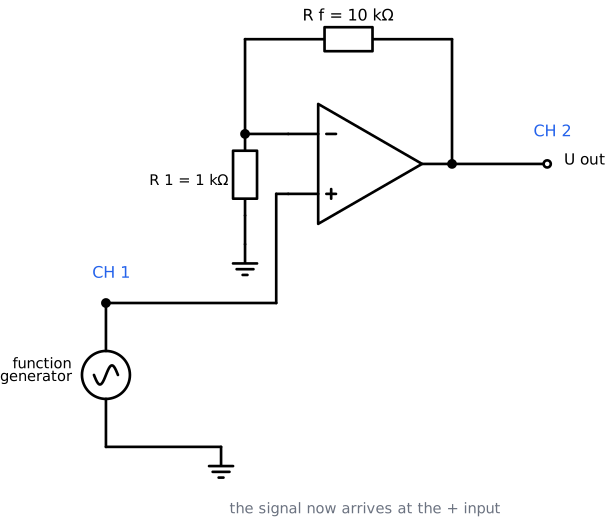
Rebuild with the signal on pin 3 this time. R 1 = 1 kΩ from pin 2 to 0 V, and R f = 10 kΩ from pin 6 back to pin 2.
Generator: sine, 1 kHz, 0,5 Vpp.
| Quantity | Calculated | Measured |
|---|---|---|
| Gain, from 1 + R f / R 1 | ||
| U in (Vpp) | ||
| U out (Vpp) | ||
| Gain, from U out / U in |
Compare the two traces with what you saw in step 2.4. What is different?
Swap R 1 and R f around, so R 1 = 10 kΩ and R f = 1 kΩ. What gain do you calculate, and what do you measure? Can this circuit ever make a signal smaller?
2.6 Adder
Now leave the generator aside and work with DC voltages you can set yourself, using the two potentiometers.
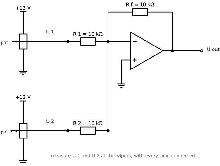
Build: each potentiometer between +12 V and 0 V, with its wiper going through a 10 kΩ resistor to pin 2. R f = 10 kΩ from pin 6 back to pin 2. Pin 3 to 0 V.
Measure the inputs, do not assume them
The 10 kΩ input resistor loads the potentiometer, so the wiper voltage is not exactly what the position of the knob suggests. Always measure U 1 and U 2 at the wipers with the circuit connected.
Set four different combinations and measure all three voltages with the multimeter.
| U 1 measured | U 2 measured | U out expected | U out measured |
|---|---|---|---|
| about 1 V | about 1 V | ||
| about 2 V | about 1 V | ||
| about 3 V | about 2 V | ||
| your own choice | your own choice |
Your output voltages are negative while both inputs are positive. Which part of the formula from the theory explains that?
Turn both potentiometers up until the output stops following your calculation. At what output voltage does it stop, and why there?
2.7 Subtractor
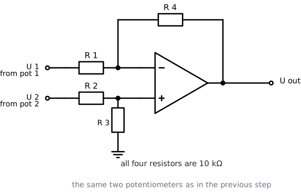
Rewire to the difference amplifier. All four resistors are 10 kΩ: R 1 from U 1 to pin 2, R 4 from pin 6 back to pin 2, R 2 from U 2 to pin 3, and R 3 from pin 3 to 0 V. The two potentiometers stay where they are.
| U 1 measured | U 2 measured | U out expected (U 2 − U 1) | U out measured |
|---|---|---|---|
| about 1 V | about 3 V | ||
| about 3 V | about 1 V | ||
| about 2 V | about 2 V | ||
| your own choice | your own choice |
Look at the row where both inputs are the same. What does the output do, and why is that useful for a sensor at the end of a long cable?
Take a picture of your finished subtractor.
2.8 Extra: comparator with an LED
Steps 2.8 and 2.9 are optional and are not graded.

Take every feedback resistor out. Put a threshold voltage from pot 1 on pin 2, the signal from pot 2 on pin 3, and an LED with a 1 kΩ resistor from the output to 0 V.
- Set the threshold with pot 1 to about 4 V and measure it.
- Turn pot 2 slowly up from 0 V and watch the LED.
| Measurement | Value |
|---|---|
| Threshold you set on pin 2 | |
| Input voltage where the LED switches on | |
| Input voltage where it switches off again | |
| Output voltage with the LED on | |
| Output voltage with the LED off |
Turn pot 2 very slowly to exactly the switching point and hold it there. What does the LED do?
2.9 Extra: pushing it past its limits
Go back to the inverting amplifier with a gain of 10.
Clipping. Set the frequency to 1 kHz and turn the input amplitude up step by step until the output stops growing.
| Measurement | Value |
|---|---|
| Input amplitude where the output stops growing | |
| Largest output amplitude you can reach | |
| Your supply voltage | |
| Difference between the two |
Slew rate. Switch the generator to a square wave at 10 kHz and look closely at the edges of the output.
3. Reflection
Write a short reflection of approximately half a page (font: Arial 9.5). Answer the following questions in your own words.
What did you learn?
Which concepts from the theory lesson did you recognise in the lab? Give a concrete example from your own measurements.
What was difficult?
Which step gave you the most trouble? How did you solve it?
Calculated against measured
Your measured gains were close to the calculated ones but not exactly equal. Name two causes, and say which one you think mattered most in your circuit.
Connection to IoT
A sensor gives you a signal between 0 V and 100 mV. The ADC of your microcontroller wants a signal between 0 V and 3,3 V to use its full range. Which circuit from this lab would you use, what gain do you need, and which two resistors would you pick from your kit?