
Lab 6: Binary Logic
1. Assignment description
In this lab you will simulate and test logic gates using an Arduino UNO R4. In part one you use four push buttons and one LED to test each logic gate one by one. In part two you connect a temperature sensor and a light sensor and use them as real-world inputs for a logic gate. An optional third part lets you build a logic gate in pure hardware using an IC chip, without any Arduino code.
The lab is built up step by step. Each step extends the program from the previous one, so do not skip steps.
What we expect:
- A working Arduino sketch for part one and two combined
- Clean and readable code with clear function names
- Completed truth tables and timing diagrams where indicated
- Photos or screenshots where indicated
- A short reflection of approximately half a page in Chapter 3
Step 2.3 is optional
Step 2.3 is not graded. It is intended for students who finish early.
2. Lab
What do we need?
- 1x Arduino UNO R4
- 1x LED (red)
- 1x 220 ohm resistor
- 4x 10K ohm resistor
- 4x push button
- Jumper wires
- Breadboard
- LM35DZ temperature sensor
- Adafruit BH1750 light sensor
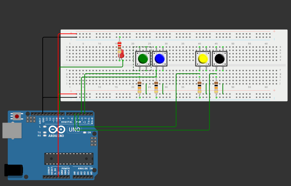
Connect the following components to the Arduino before you start:
- 4x push button connected to digital pins 2 (button A), 3 (button B), 4 (button Left) and 5 (button Right)
- 1x LED with a 220 ohm resistor connected to digital pin 9 (F)
Each push button has a pull-down resistor connected to GND. This means the pin reads LOW when the button is not pressed and HIGH when it is pressed.
Use the schematic below:
2.1 Logic gates in software
In this part you use four push buttons to test all logic gates. Button A (pin 2) and button B (pin 3) are the inputs for the active logic gate. Button LEFT (pin 4) switches to the previous gate and button RIGHT (pin 5) switches to the next gate. The LED (pin 9) shows the output of the active gate.
The program cycles through the following gates in order: NOT, AND, OR, NAND, NOR, XOR, XNOR.
Info
The NOT gate only uses input A. Input B is ignored.
Below is the starting structure for your sketch. Read it carefully before you start adding code.
// Pin definitions
const int PIN_A     = 2;
const int PIN_B     = 3;
const int PIN_LEFT  = 4;
const int PIN_RIGHT = 5;
const int PIN_LED   = 9;

// Gate names
String gateNames[] = {"NOT", "AND", "OR", "NAND", "NOR", "XOR", "XNOR"};
int totalGates = 7;
int activeGate = 0;

void setup() {
  Serial.begin(9600);
  pinMode(PIN_A,     INPUT);
  pinMode(PIN_B,     INPUT);
  pinMode(PIN_LEFT,  INPUT);
  pinMode(PIN_RIGHT, INPUT);
  pinMode(PIN_LED,   OUTPUT);
}

void loop() {
  // put your main code here, to run repeatedly:
}
Write the following functions:
computeGate(int gate, int a, int b)returns the output of the active gate. Use aniforswitchstatement to handle each gate separately. Use the truth tables from the theory to determine the output for each combination of A and B.handleNavigationButtons()reads the LEFT and RIGHT buttons and updatesactiveGate. Make sure the gate index does not go below 0 or above 6.
In loop(): read the inputs, call computeGate, update the LED and print the current state to the serial monitor in the following format:
Gate: AND | A: 1 B: 0 | Output: 0Add a small delay of 200 ms to prevent the output from scrolling too fast.
Truth tables, timing diagrams and proof of output
Fill in the truth table for each gate after you have tested it. Take a picture of the timing diagram. It must be drawn by hand for each gate. Upload a picture of the output LED for each input combination and place it in the notes below the table. The inputs (button A and B) must be visible in the picture.
NOT gate
| A | F |
|---|---|
| 0 | |
| 1 |
AND gate
| A | B | F |
|---|---|---|
| 0 | 0 | |
| 0 | 1 | |
| 1 | 0 | |
| 1 | 1 |
OR gate
| A | B | F |
|---|---|---|
| 0 | 0 | |
| 0 | 1 | |
| 1 | 0 | |
| 1 | 1 |
NAND gate
| A | B | F |
|---|---|---|
| 0 | 0 | |
| 0 | 1 | |
| 1 | 0 | |
| 1 | 1 |
NOR gate
| A | B | F |
|---|---|---|
| 0 | 0 | |
| 0 | 1 | |
| 1 | 0 | |
| 1 | 1 |
XOR gate
| A | B | F |
|---|---|---|
| 0 | 0 | |
| 0 | 1 | |
| 1 | 0 | |
| 1 | 1 |
XNOR gate
| A | B | F |
|---|---|---|
| 0 | 0 | |
| 0 | 1 | |
| 1 | 0 | |
| 1 | 1 |
Paste your full code here.
2.2 Real-world inputs
In this part you connect a temperature sensor and a light sensor. Their values are used as logic inputs for an AND gate. The LED turns on when both conditions are met.
Keep the previous setup and code. You will only extend the functionality of the current program.
What do we need?
- 1x LM35DZ temperature sensor
- 1x Adafruit BH1750 light sensor
- Jumper wires
Connect the components to the Arduino. You are responsible for finding the correct datasheets and connecting the components correctly.
- Connect the LM35 to pin A0
- Connect the BH1750 via I2C
Ask the user via Serial Console which part they want to run. If the user enters 1, run the code from step 2.1. If the user enters 2, run the code for this step. If the user enters menu, show the menu again.
How the inputs work:
The sensor values are converted to a logical 0 or 1 based on a threshold:
| Input | Sensor | Logical 1 when |
|---|---|---|
| A | LM35 temperature sensor | Temperature >= 25°C |
| B | BH1750 light sensor | Light level >= 100 lux |
The LED behaves according to the following truth table:
| A (temp >= 25°C) | B (lux >= 100) | LED |
|---|---|---|
| 0 | 0 | 0 |
| 0 | 1 | 0 |
| 1 | 0 | 0 |
| 1 | 1 | 1 |
Which logic gate does this truth table represent?
Write the following functions:
readTemperature()reads the LM35 and returns the temperature in degrees Celsius. Use the formula below:
float voltage     = analogRead(A0) * (5.0 / 1023.0);
float temperature = voltage * 100.0;readLight()reads the BH1750 and returns the light level in lux.applyThresholds(float temp, float lux)returns a struct with two boolean fields:aandb. These are based on the thresholds above.
In the part two section of loop(): read both sensors, apply the thresholds, compute the gate output and update the LED. Print the following to the serial monitor every 500 ms:
Temp: 23.4C (A=0) | Light: 134 lux (B=1) | Output: 0Cover the light sensor with your hand so that B becomes 0. Take a screenshot of the serial monitor showing a change in output.
Hold something warm near the temperature sensor so that A becomes 1, combined with a well-lit environment so B is also 1. Take a picture of the LED turning on.
What would change if you replaced the AND gate with an OR gate? Describe in one sentence what the LED would do differently.
Paste your full code here.
2.3 Extra: Logic gate IC
This step is optional and is not graded.
In this part you build a logic gate in pure hardware without any Arduino code. You use a 74HC08 IC, which contains four AND gates in a single chip.
What do we need?
- 1x 74HC08 IC
- 2x push button
- 1x 220 ohm resistor
- 4x LED (red)
- Jumper wires
- Breadboard
- 5V power supply (use the 5V pin of the Arduino)
Connect the IC according to its datasheet. Connect two push buttons as inputs and the LED as output. Power the IC with 5V and connect GND.
Does the LED behave the same way as your AND gate in software? Take a picture of your setup.
What is the advantage of using a dedicated IC instead of an Arduino for this kind of logic?
3. Reflection
Write a short reflection of approximately half a page (font: Arial 9.5). Answer the following questions in your own words:
What did you learn?
Which concepts from the theory did you recognise in the lab? Give a concrete example.
What was difficult?
Which step gave you the most trouble? How did you solve it?
What would you do differently?
If you had to redo this lab, what would you approach differently?
Logic gates in software
In part one you implemented all logic gates in software. Which gate was the most difficult to implement and why?
Real-world sensors as logic inputs
In part two you used real sensor values as logic inputs. Can you think of a practical IoT application that works in a similar way? Describe it briefly.
Software vs hardware
What is the difference between simulating a logic gate in software and building one with a physical IC? What are the advantages and disadvantages of each approach?